How it all began:
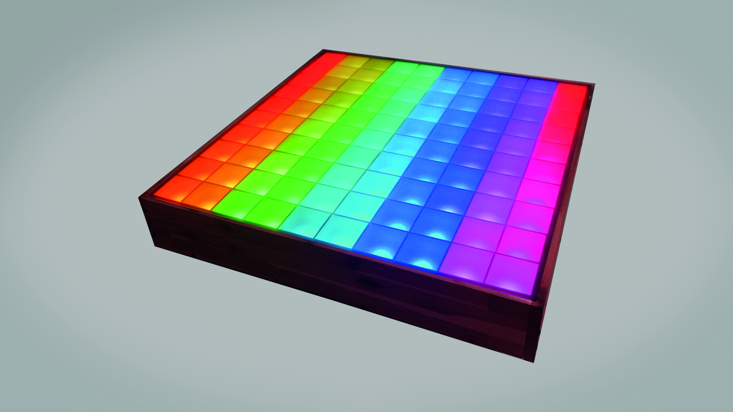
At the beginning of 2015, when I was still at school, I had to decide on a project/theme that I wanted to work on for the next year, a so-called final year project. My topic had been clear to me for a long time! It should be about the development, the construction and the programming of this LED table. See for yourself...
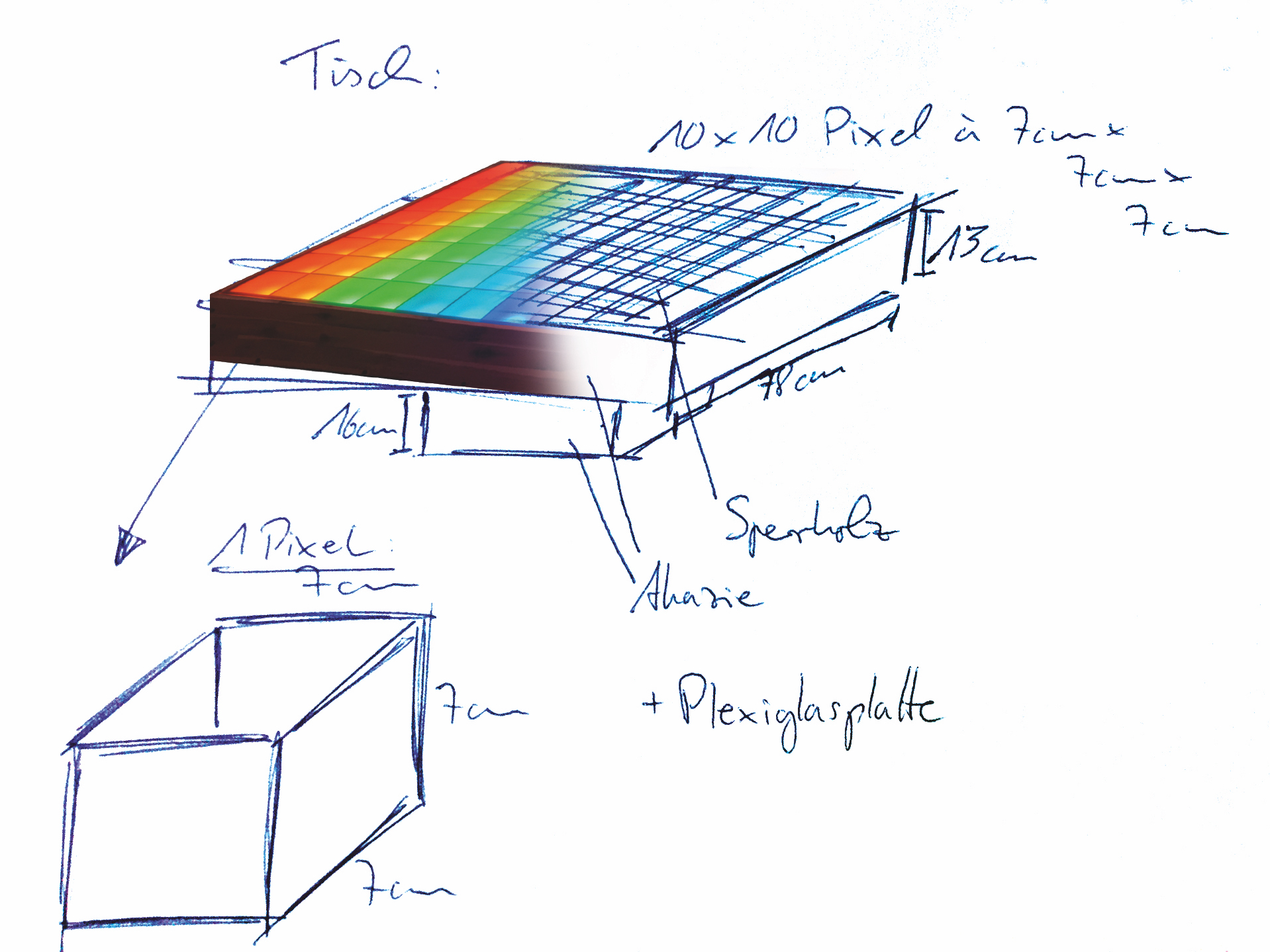
Of course it all started with a sketch, which I adapted to my ideas, wishes and expectations. The
design had been clear to me relatively fast, I wanted to build an elegant, square but simple table,
which should have a good height for a sofa side table. In my case it turned out to be 29cm incl.
foot, which turned out to be quite suitable afterwards.
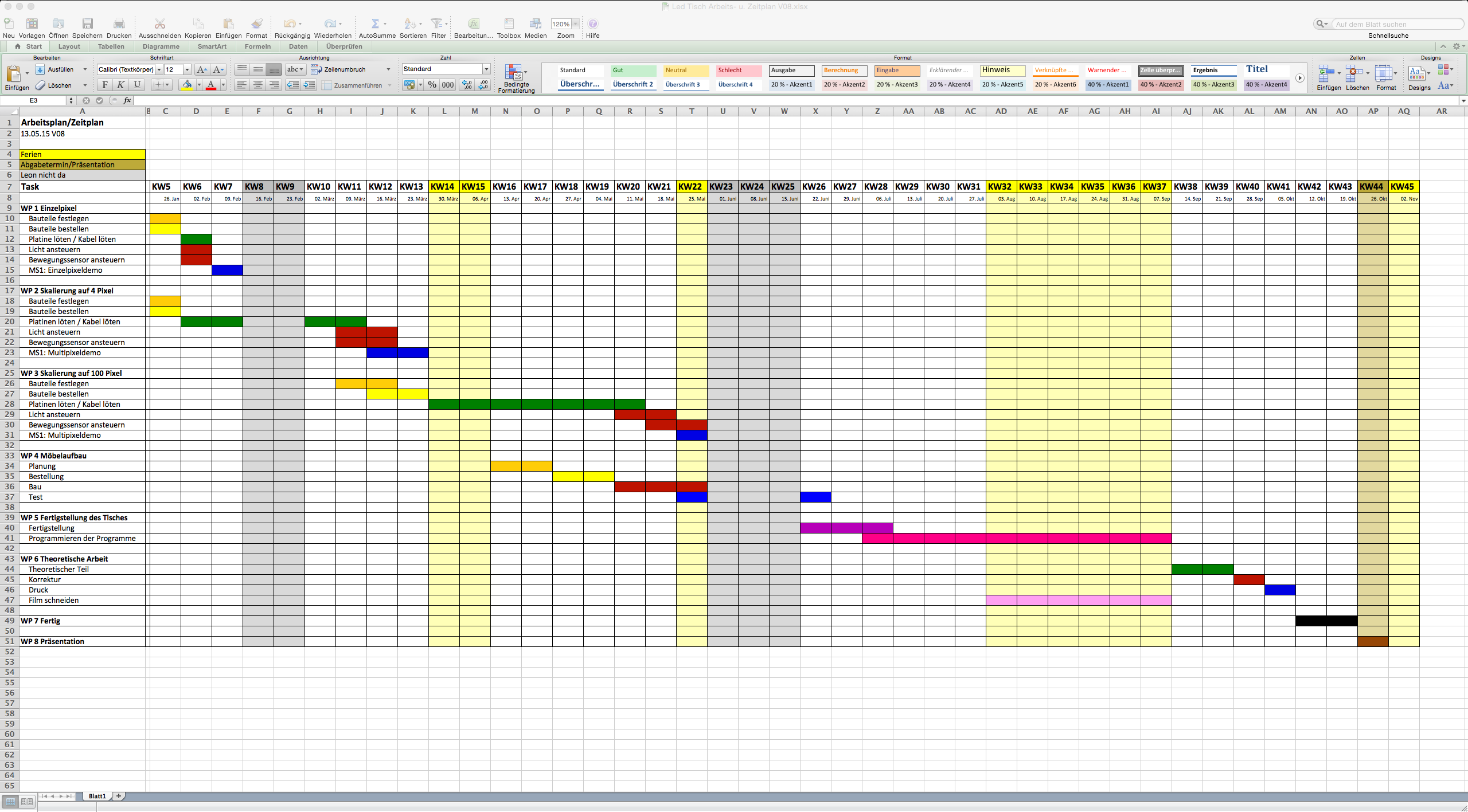
And what is almost as important as the idea itself? Yes, exactly to have a plan how to implement the
whole thing at all! I did this by creating an Excel spreadsheet in which I divided my available time
into calendar week blocks and then roughly drew a picture of when and when I planned the individual
steps. If I deviated later from the plan, I looked where I could catch the lost time again and
corrected the plan accordingly, so that it always remained current and I could also continue to hold
to it. For me this was an important point, because I had the overview from the beginning and never
got the feeling "Oh I still have so much time anyway, I allow myself a break" and I therefore always
remained active. All in all I was able to keep the plan over the year quite well.
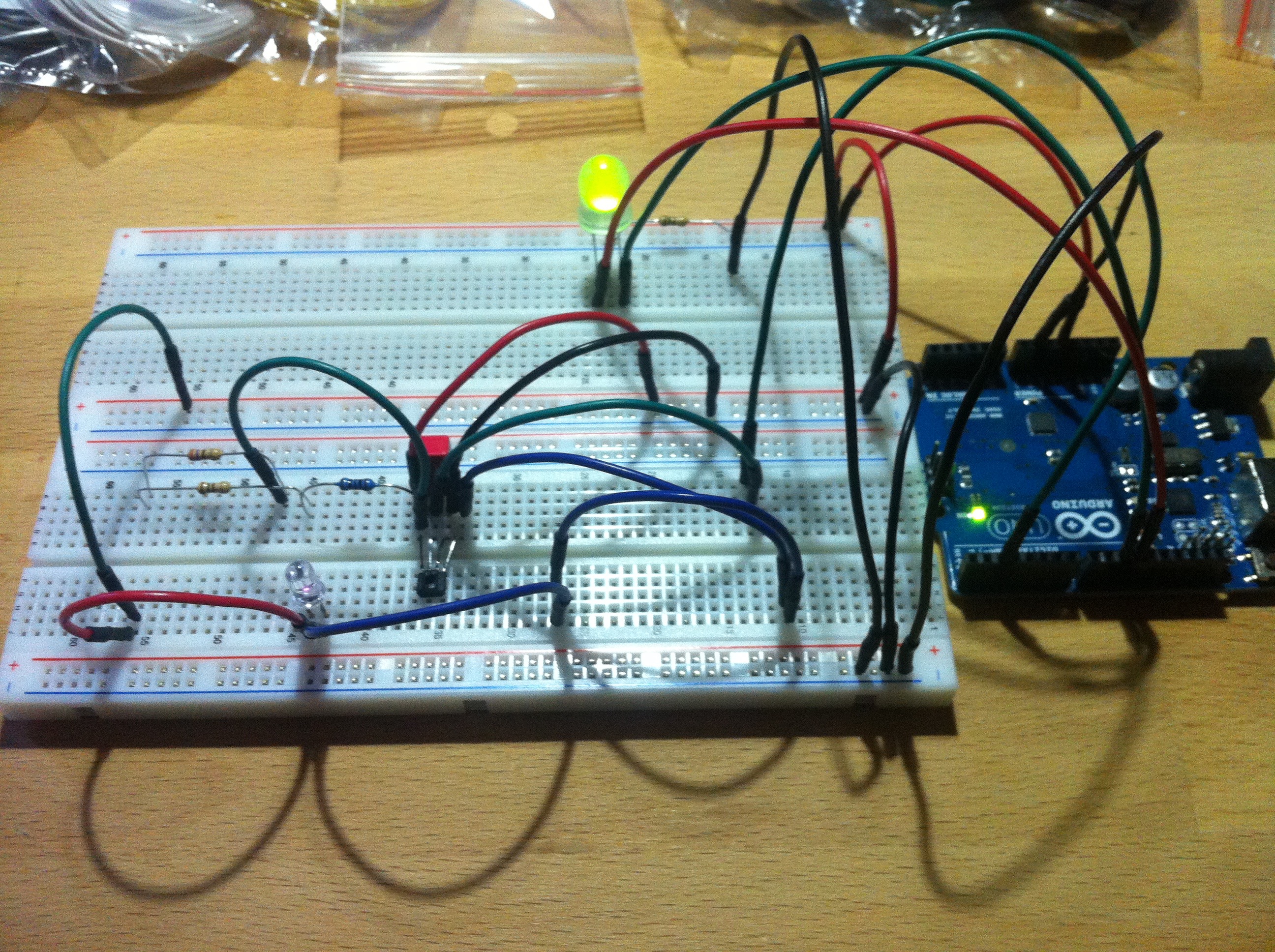
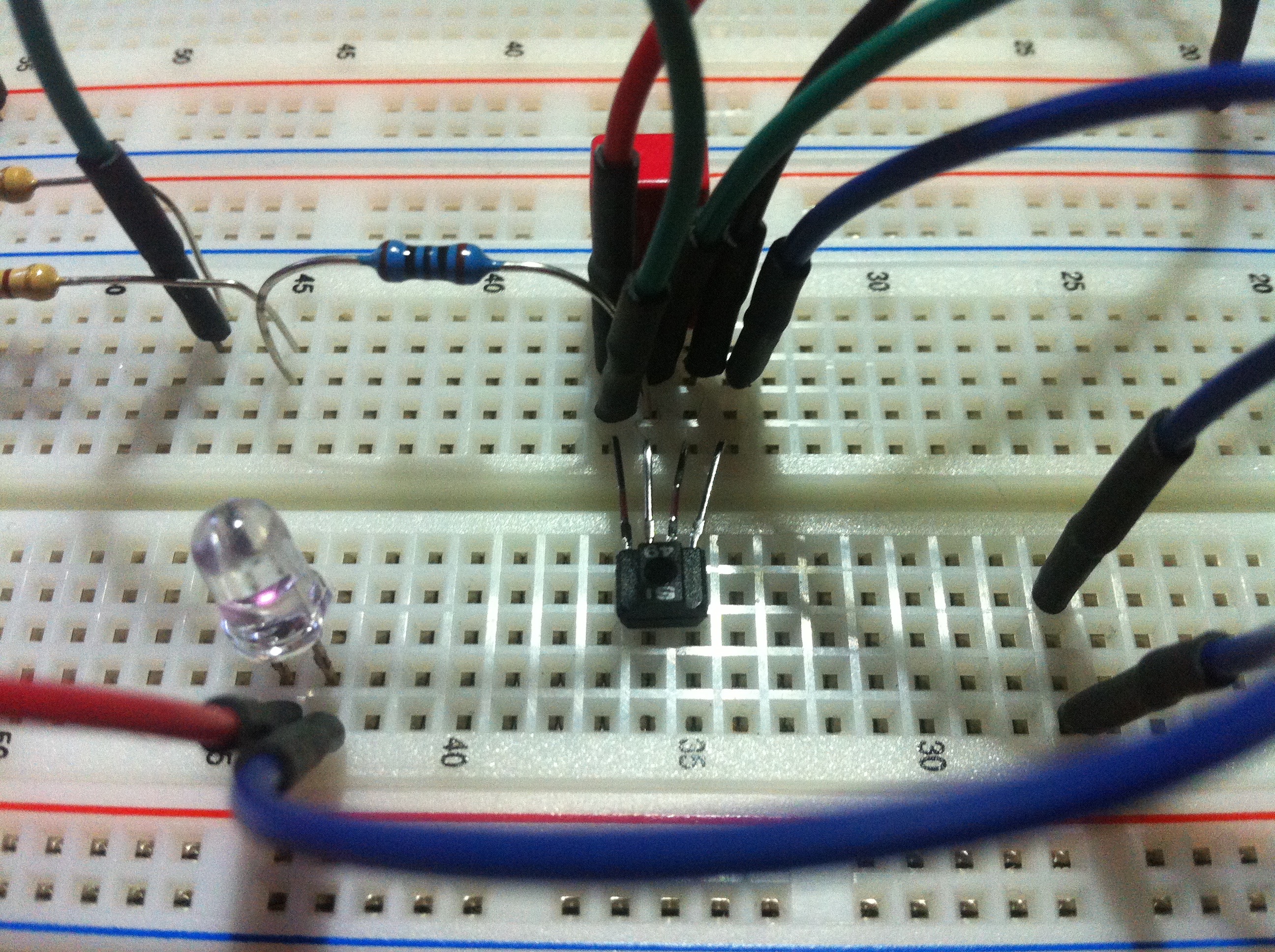
So when I had a rough idea how everything should look like in the end, I started to develop a simple
prototype, consisting of an infrared LED (940nm), an infrared sensor (IS471F) with a small 0.33μF
capacitor and resistors for the IR LED (as described in appropriate datasheet) and a large two-color LED, also with series
resistor. For controlling the prototype I used a Arduino Uno, just like I wanted to use it later for the
finished project. The shown circuit should illustrate the functionality of the basic principle. The
aim was that as soon as a reflecting surface (e.g. a hand) moved over the IR-LED and reflected the
emitted infrared light back onto the IR-Sensor, the big LED changed its color from green to red and
the whole thing was controlled by the Arduino Uno. The trick with the whole thing, why I used
exactly this special IR sensor and no other one, was that it controls the IR LED itself with a
certain frequency and that therefore only the infrared light reflected by the IR LED with the same
frequency is "accepted" by the IR sensor and therefore infrared light from other sources of
interference such as the sun can be easily eliminated. So far everything has worked fine.
(Click on the picture and browse for more PHOTOS and VIDEOS!)
(Click on the picture and browse for more PHOTOS and VIDEOS!)
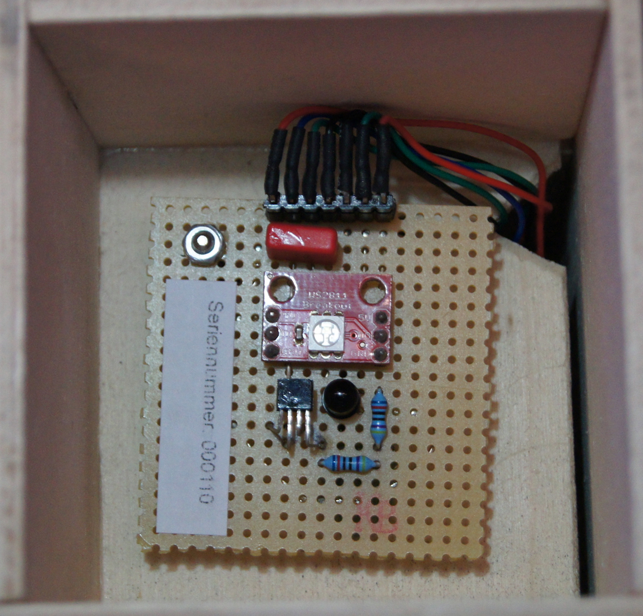
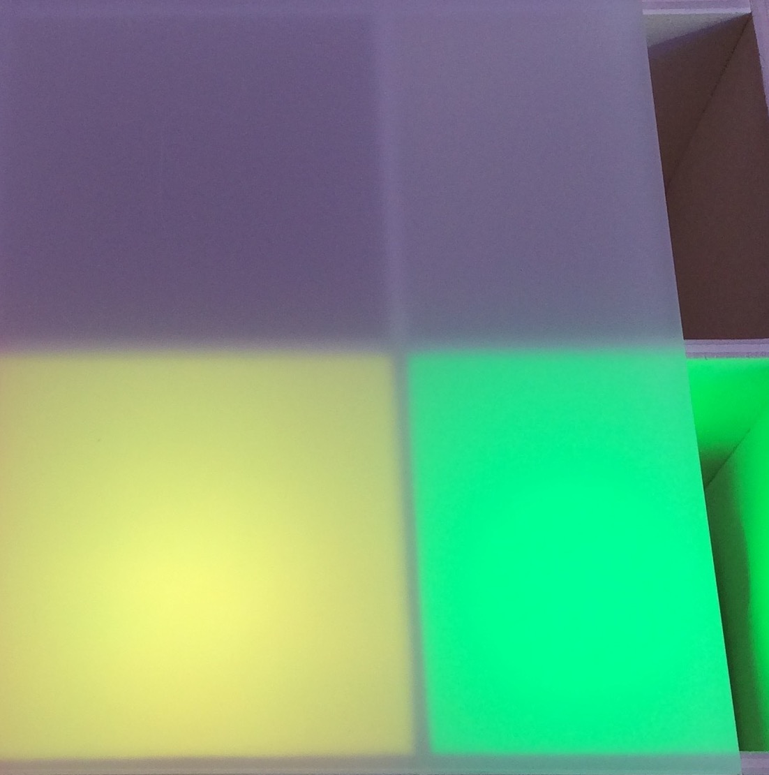
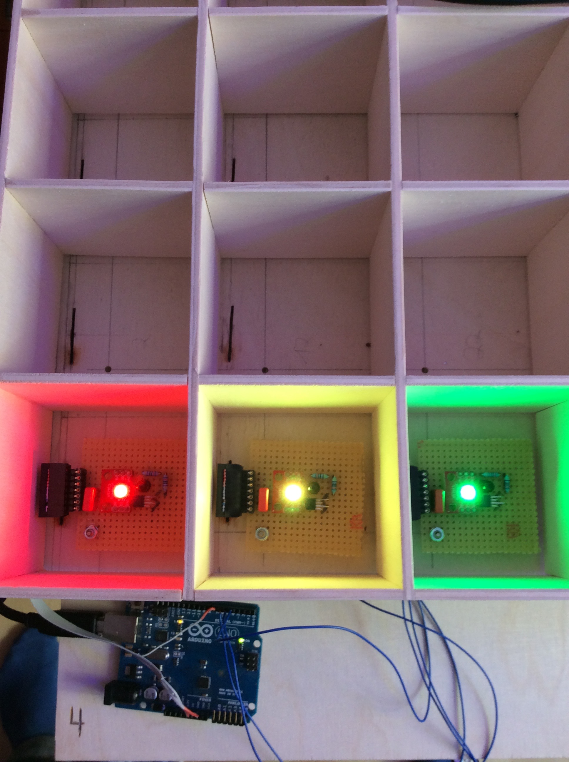
After that, I immediately started to design some finished board prototypes, which in the end looked
like pictured. To be exact there were 4 of them, because to be able to test these PCB prototypes I
built a small model consisting of 2x2 pixels. For the construction I used simple 4mm thick poplar
plywood, which I cut to size, so that every single pixel shaft had the floor dimensions 7x7cm and a
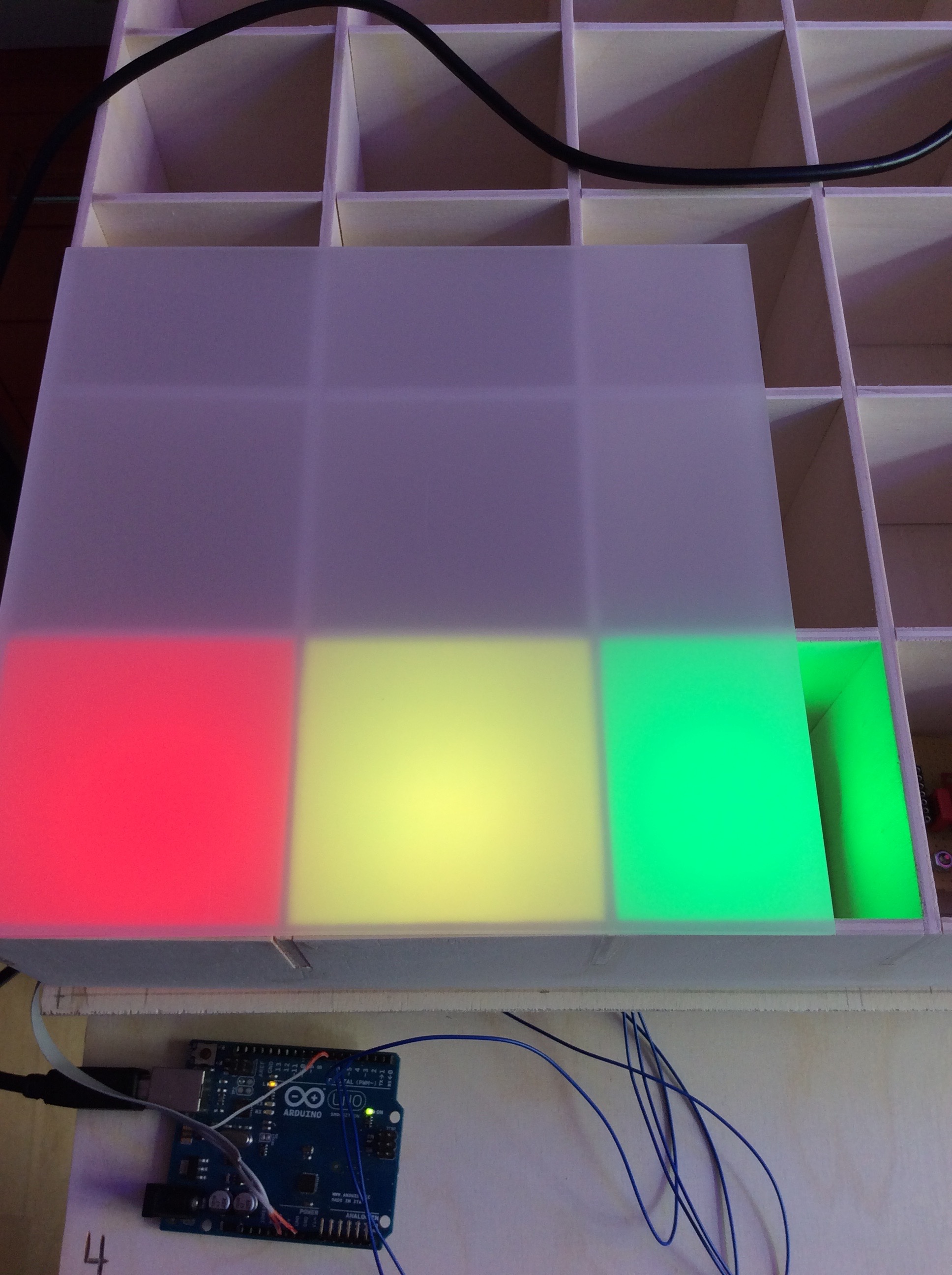
height of 7cm. Now I could try out how the infrared reflection technique behaves in the 4-pixel
prototype, since the infrared light radiated upwards naturally already reflected on the side walls
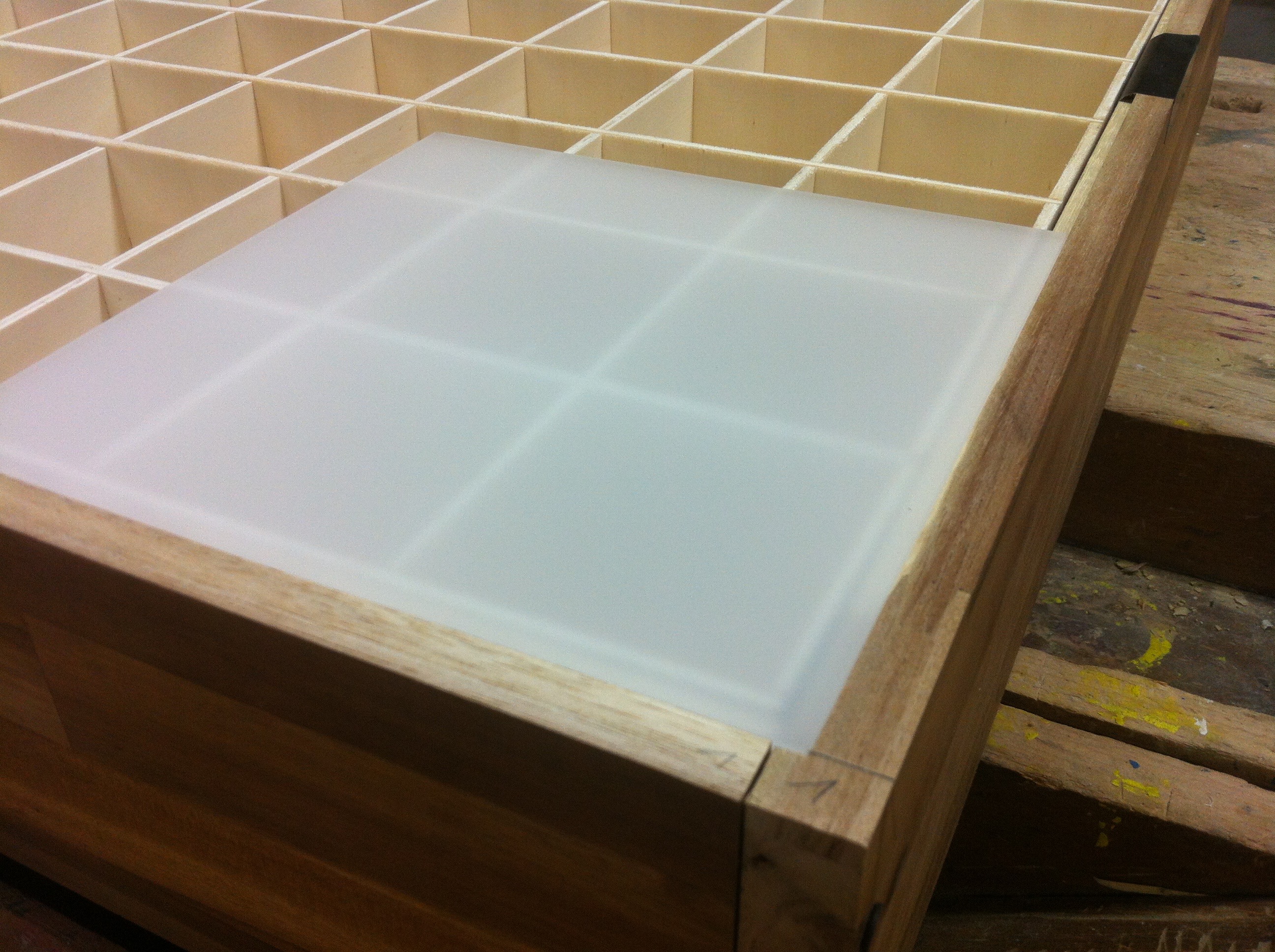
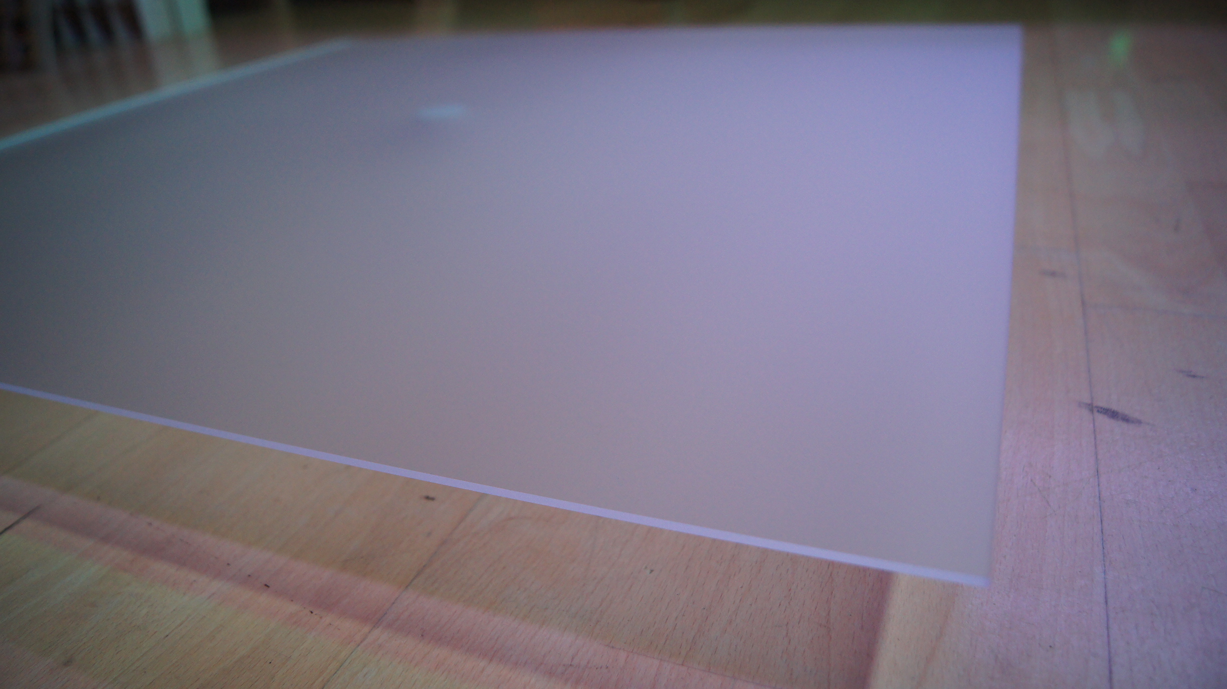
and above all also on the milky Plexiglas disk, which should later form the surface. Therefore I
tried different IR-LEDs with different beam angles. The goal was that the infrared light reflected
on the IR sensor with Plexiglas disk but without a hand on top was not enough to switch the IR
sensor (0V), but as soon as I put a hand (or similar) on the Plexiglas disk, the IR sensor should
give me directly a digital ON signal (5V). For this I tested many different combinations of IR-LEDs
and resistors, Plexiglas with different light transmission levels and different colors as background
under the PCB... (see pictures) Finally I decided for: a 940nm IR-LED with a beam angle of 40°, two
470 Ohm resistors in series, a 3mm satin colorless Plexiglas disk with a light transmission of about
92% and no color as background under the boards.

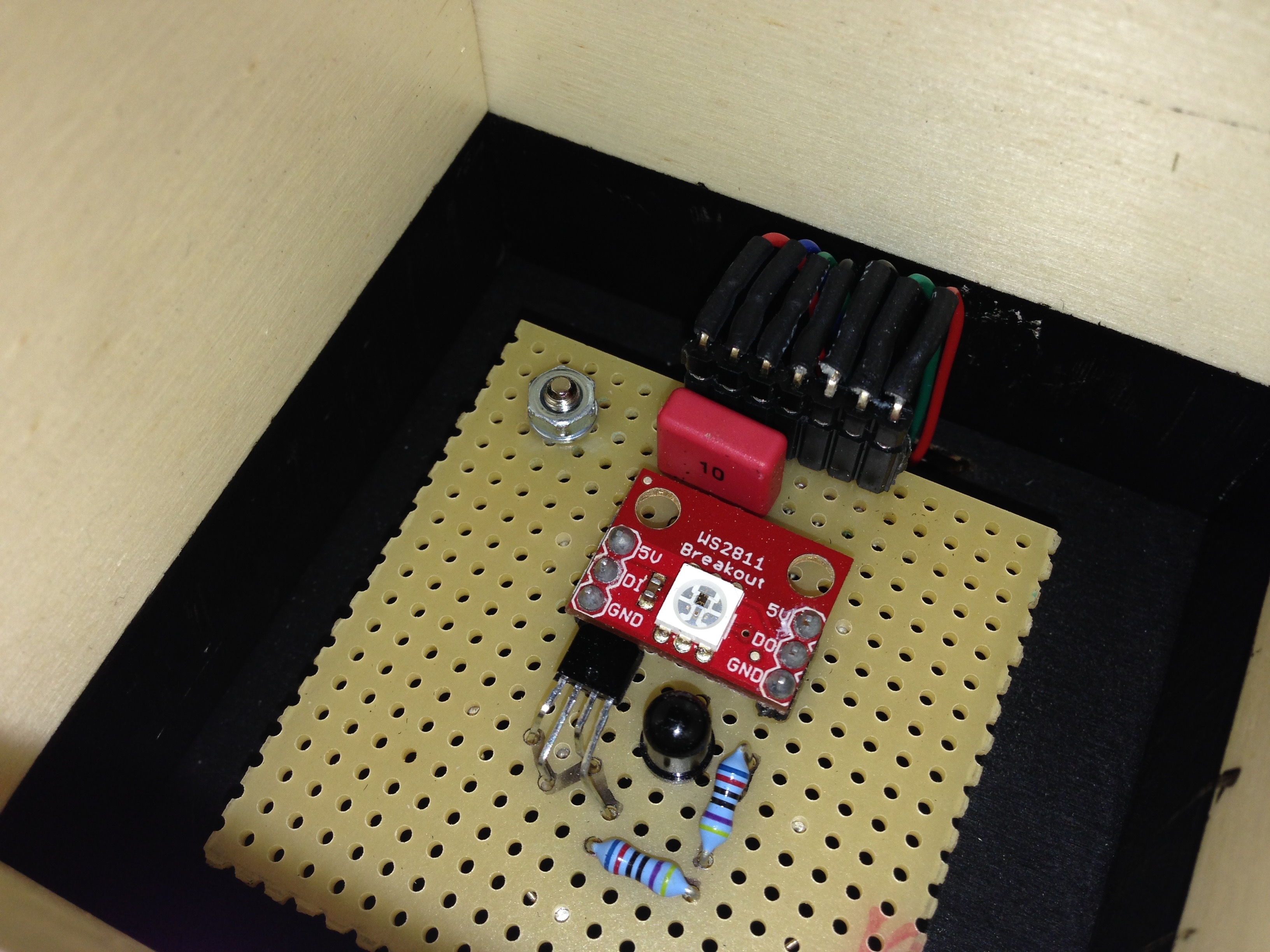
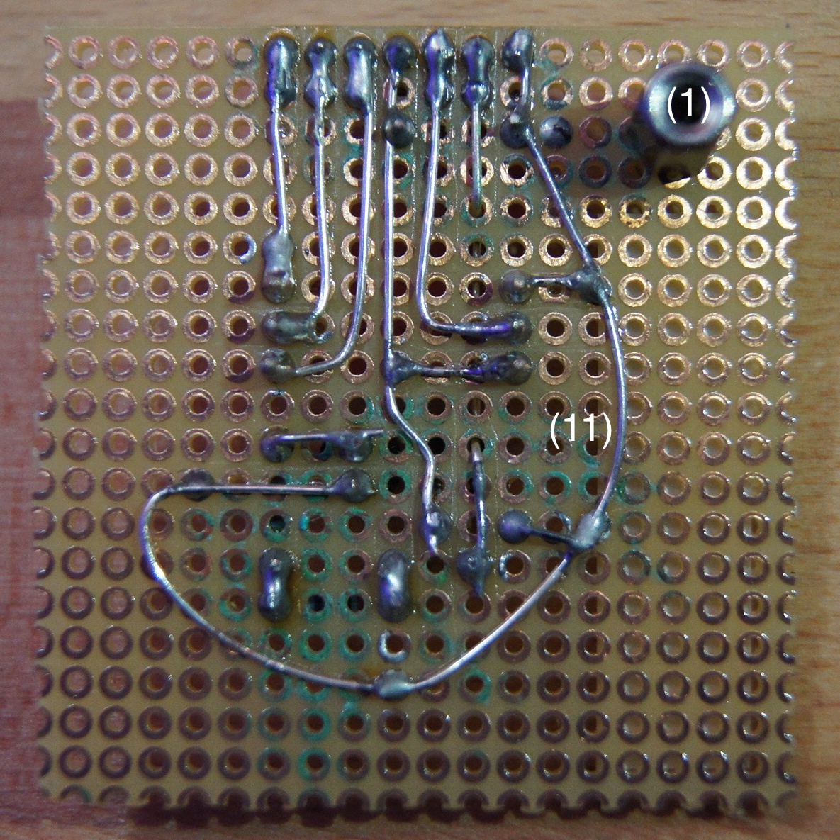
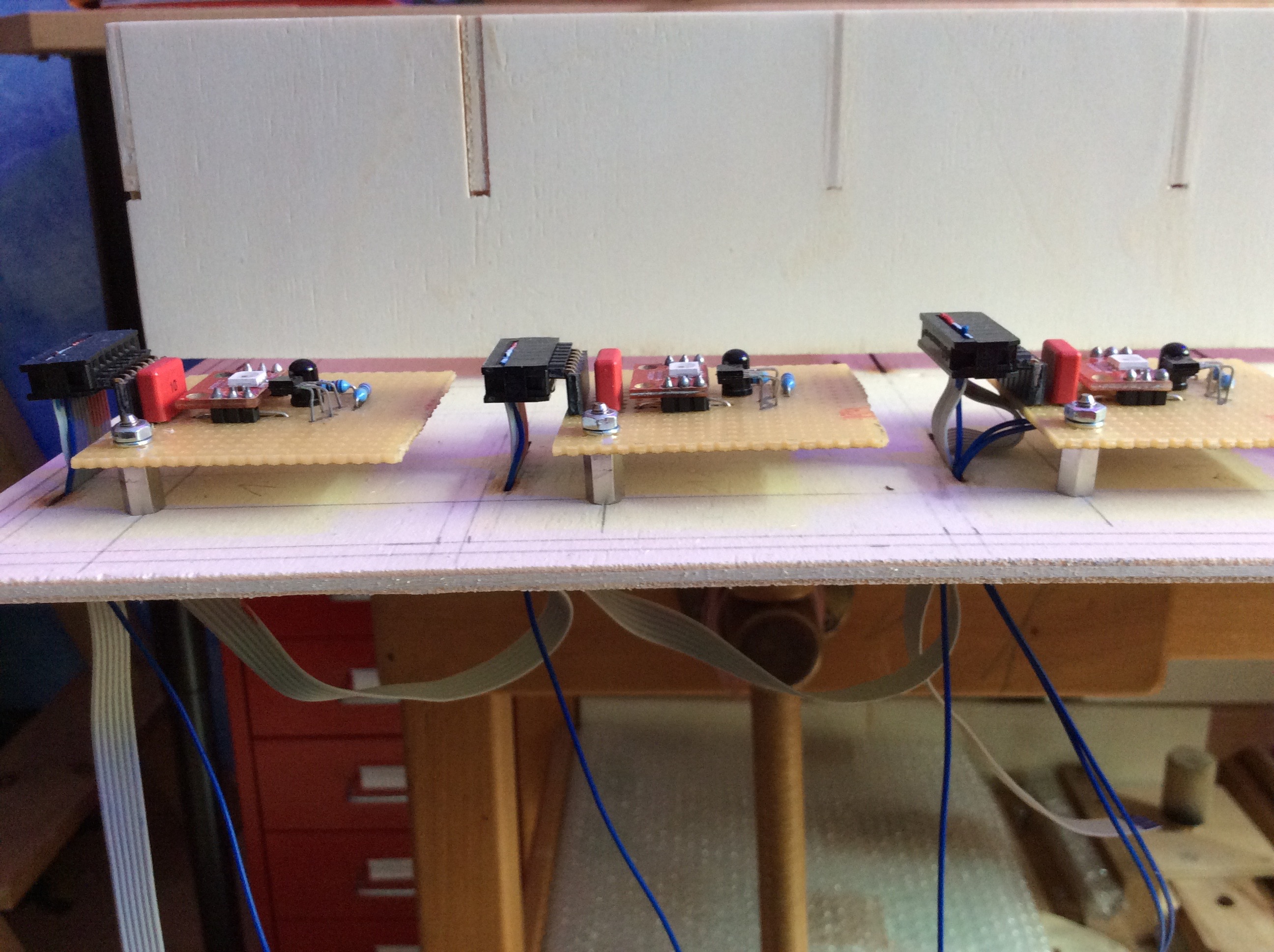
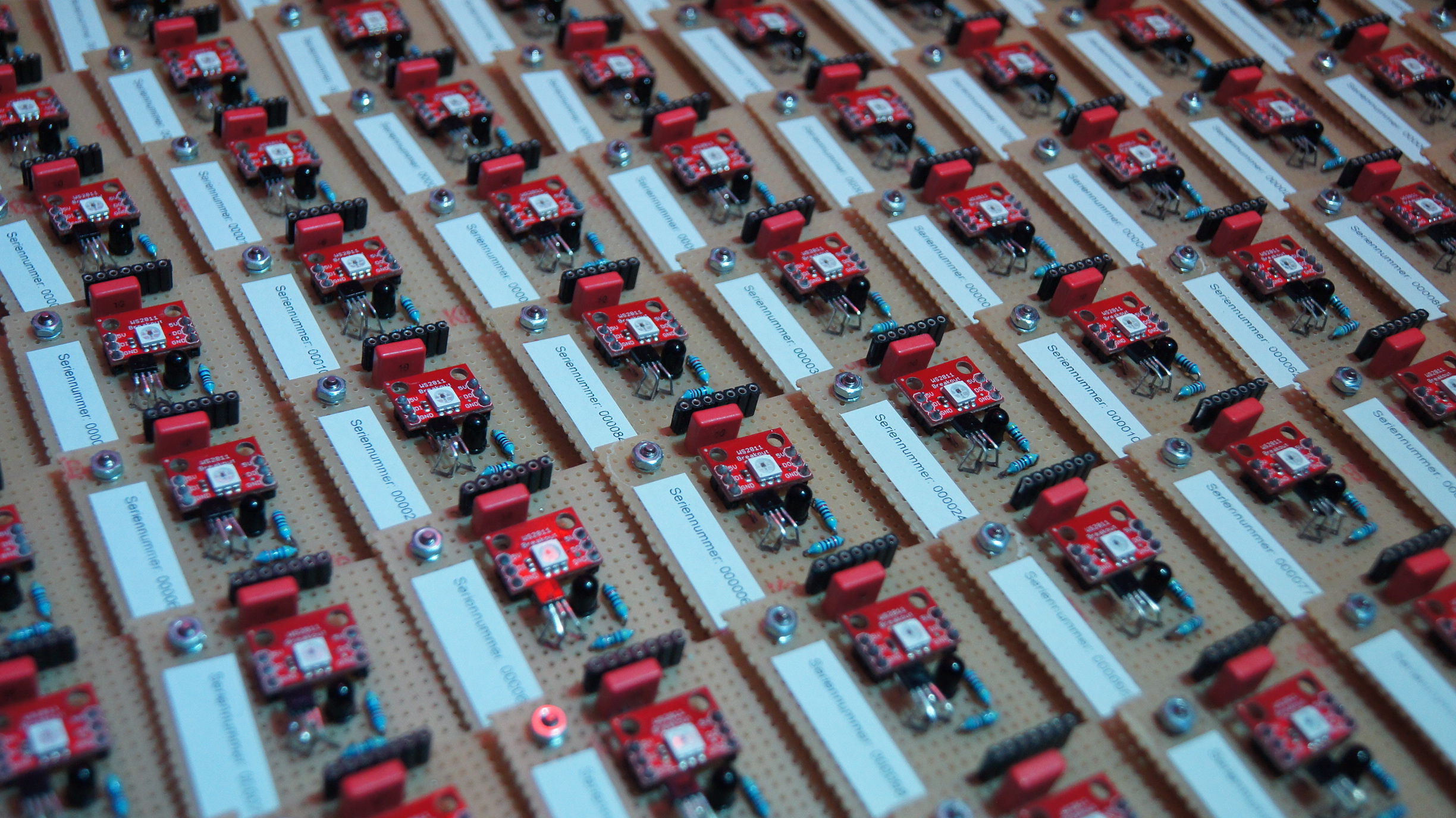
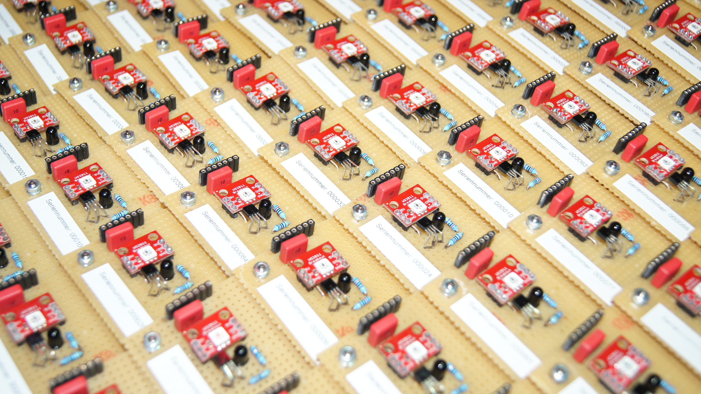
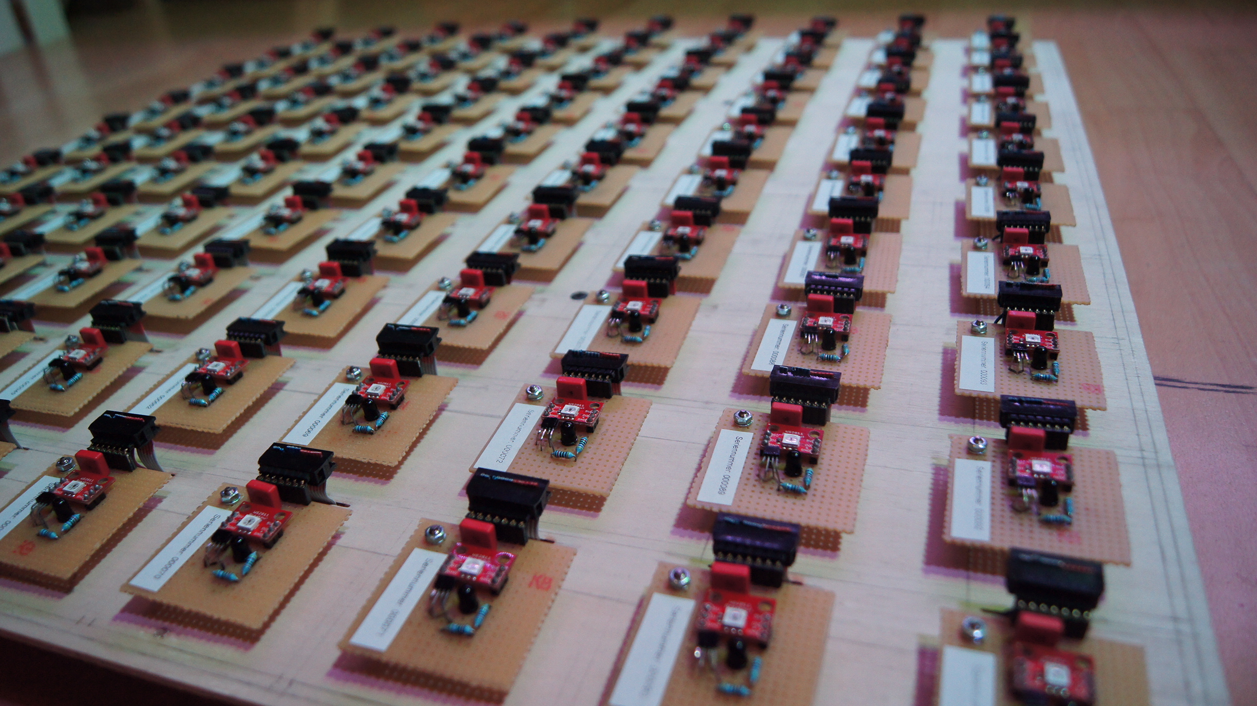
The individual components installed on the finished circuit board were finally: 1] A simple mounting
of the board on a spacer made of metal, which was connected to the substrate. 2] A pin header
connector with which the first board was connected to the second, the second to the third, and so
on. 3] The hole grid board itself. 4] A 33μF capacitor for smoothing the board voltage. 5] The IS471F IR-Sensor [6] The finished WS2811/12 RGB-LED Board [7] The looped through contact pins of the
WS2811/12 RGB-LED: 5V IN; Data IN; GND; 5V OUT; Data OUT; GND [8] One 940 nm IR-LED with a beam
angle of 40° [9] Two 470 Ohm resistors for the IR-LED [10] And another simple board identifier, so
that in case of later defects I simply keep track of which one has already been replaced and which
one has not. Fortunately many were not;) 11] On the underside of the board you can see the soldered
connections of the individual components, which were arranged with the greatest possible efficiency,
as simply as possible and nevertheless well chosen.
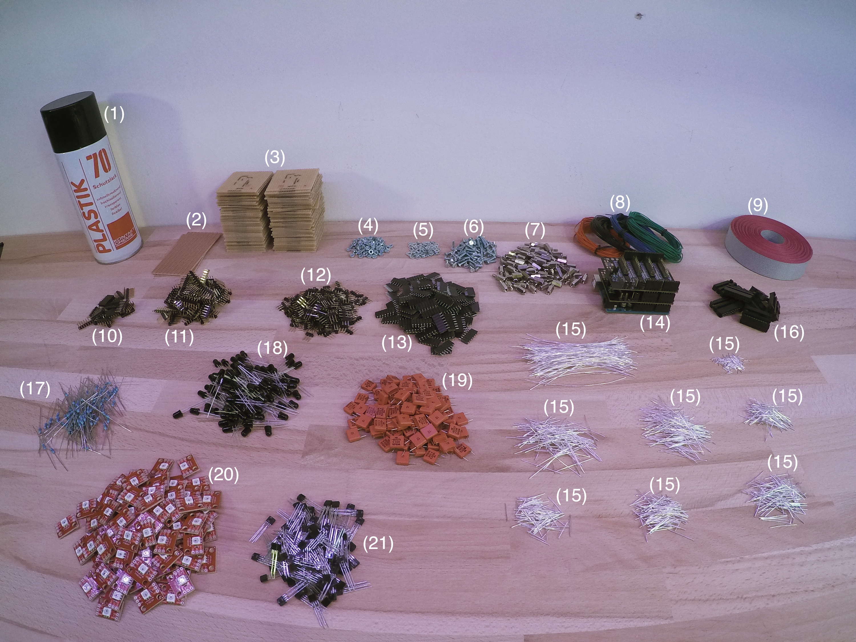
Now that I knew exactly which parts I needed, I ordered all of them and most of them 100 pieces
(actually I even ordered everything 110 times to make sure that I have spare parts in case a part
breaks down!). What I needed now was everything: A. The boards with the ribbon cable connectors [14]
The brain of the whole, the Arduino Uno with two Macetech Centipede Shield Extension boards [15] Prepared wires in
different lengths to connect the single contacts on the bottom side of the boards [16] The ribbon
cable connectors [17] The 470 Ohm resistors [18] The 940nm IR-LEDs [19] The 33μF capacitors [20] The
finished WS2811/12 RGB-LED Boards [21] And the IS471F IR-Sensors.
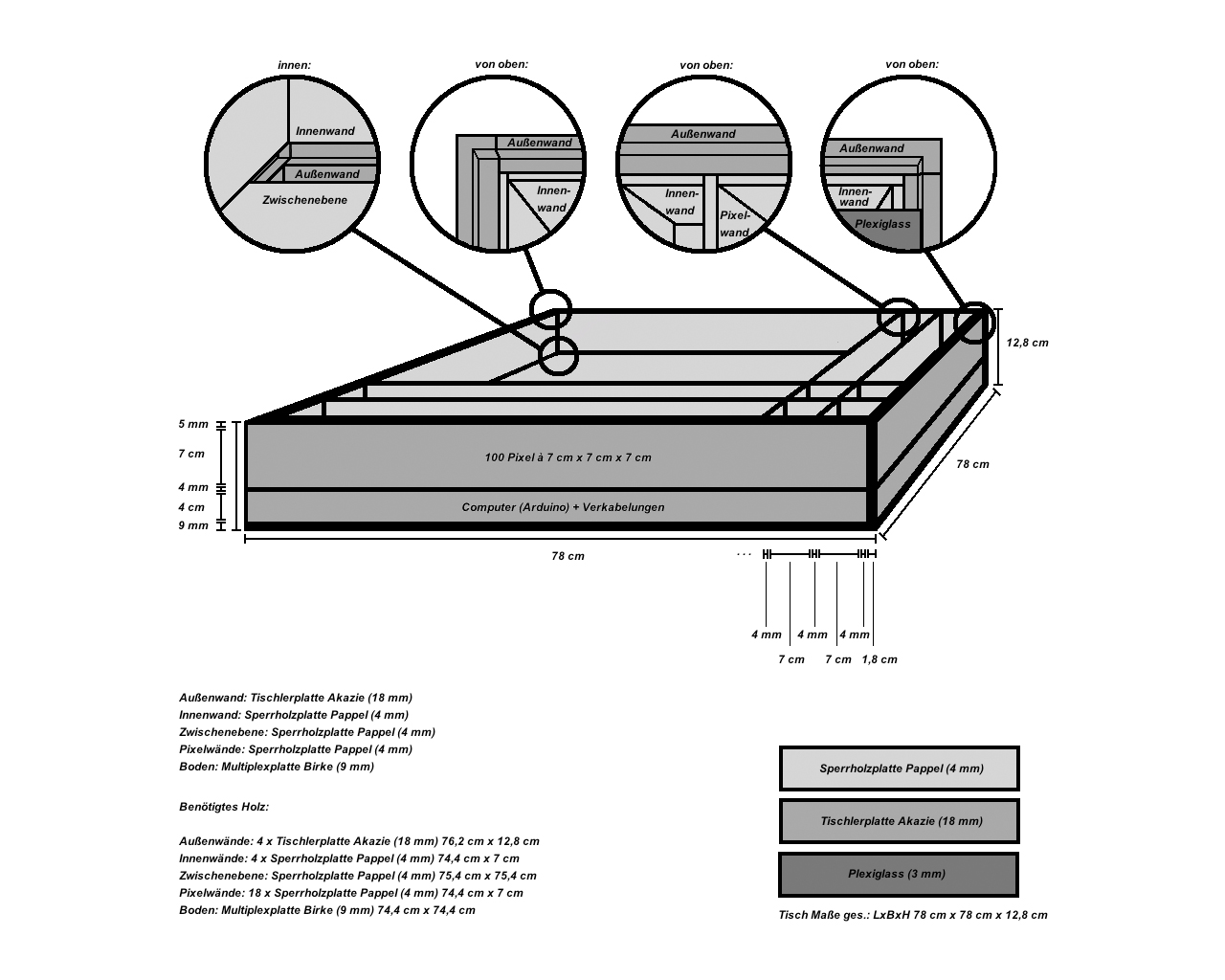
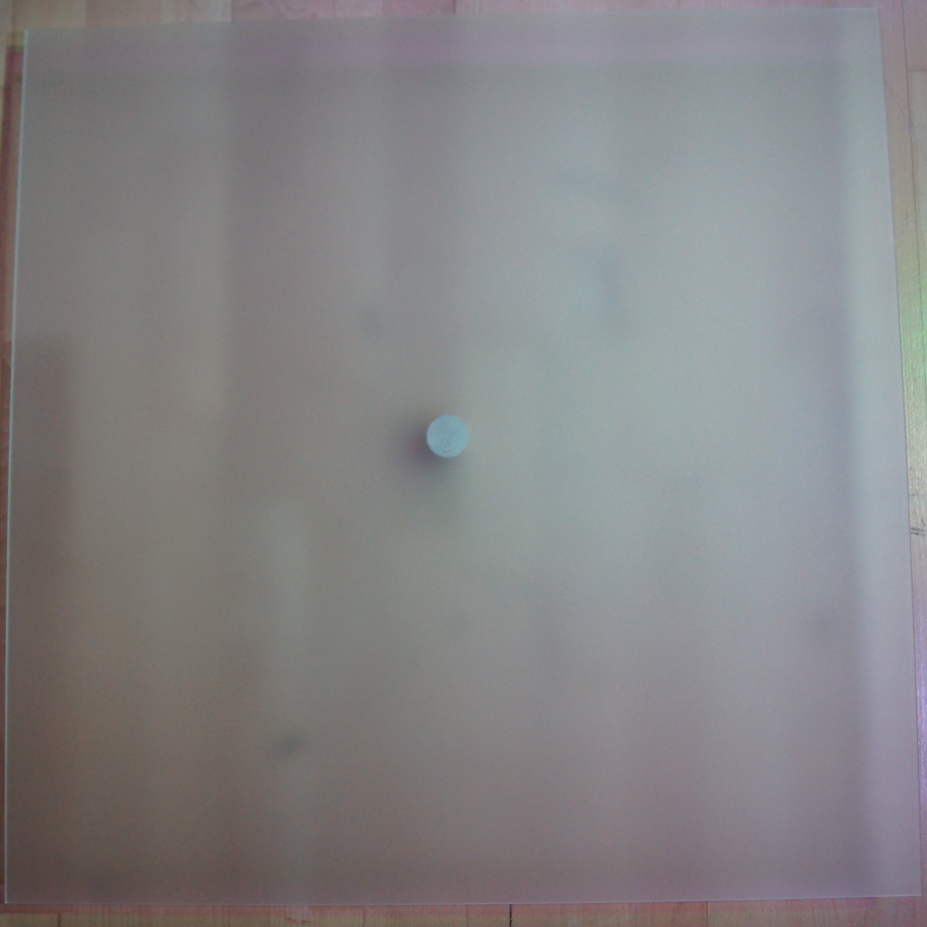
When now the whole technical functioned more or less perfect, I had to wait for the orders and I
could be sure that it will work later, I started with the sketch of the wooden frame. As already
mentioned, the table should be square, have a good height as a sofa side table and look reasonably
elegant. The result was the illustrated sketches including a sketch for a single sinker shaft. The
wood I wanted to use was once poplar plywood (4mm) for the grid and the intermediate floor, a 9mm
poplar plywood board for the floor and acacia wood core board (18mm) for the frame and on top the
3mm satin colorless plexigal disc.
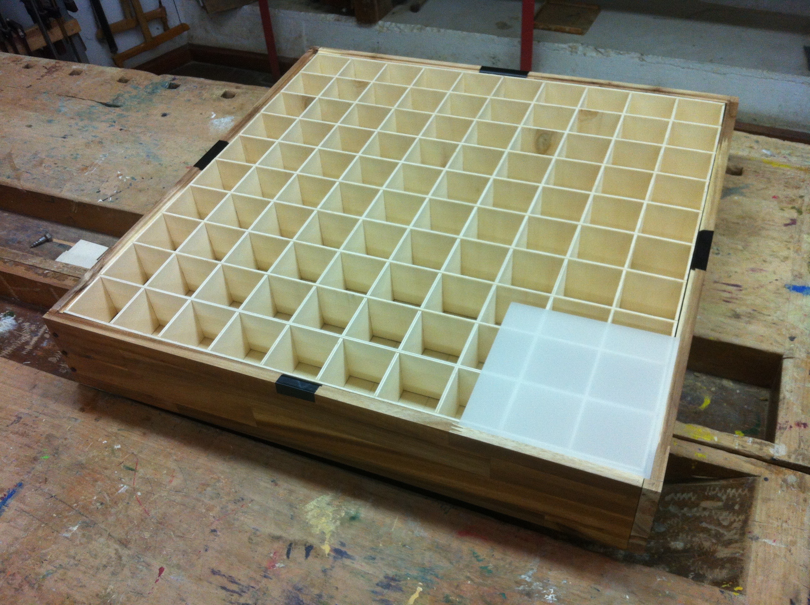
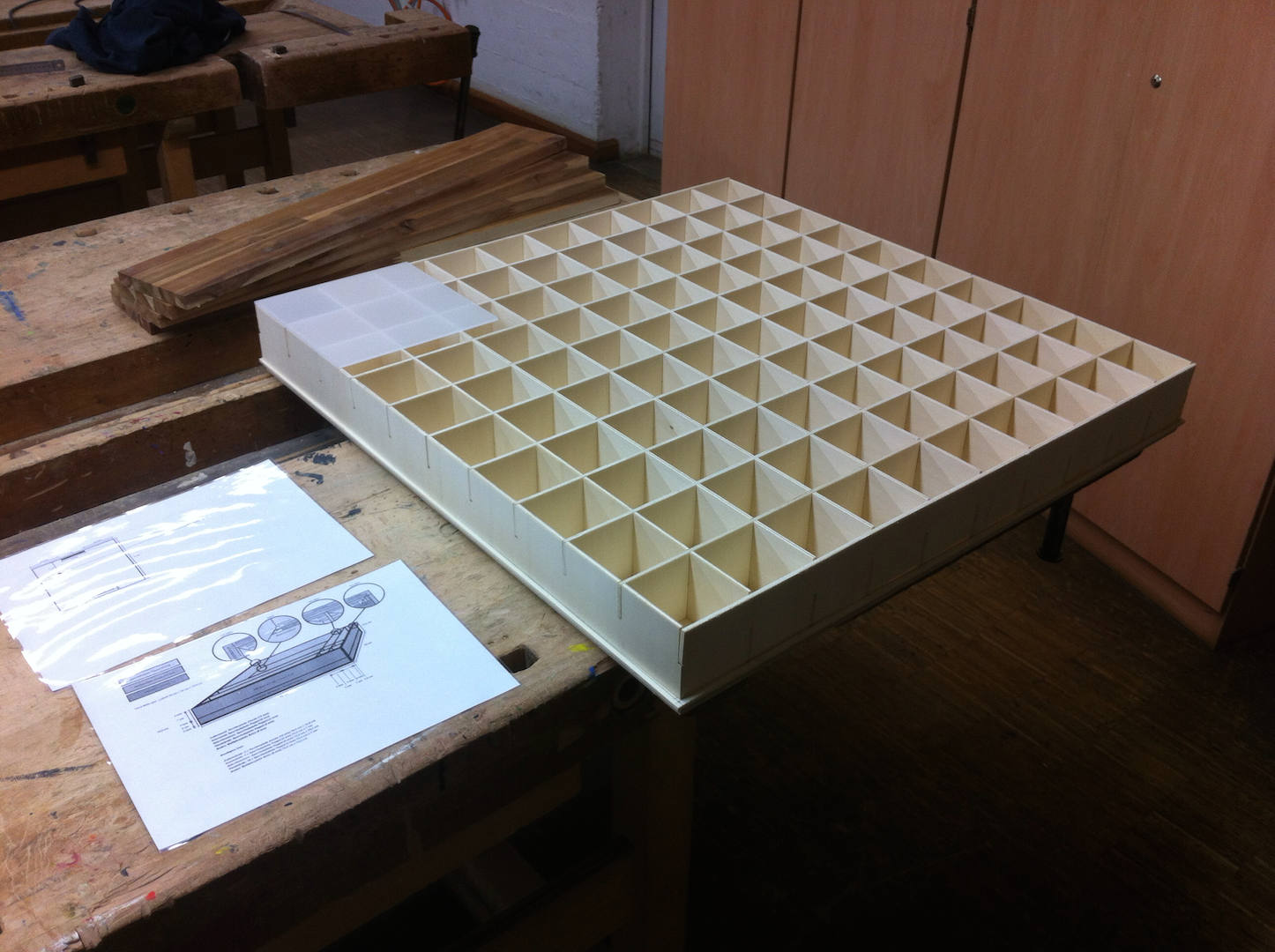
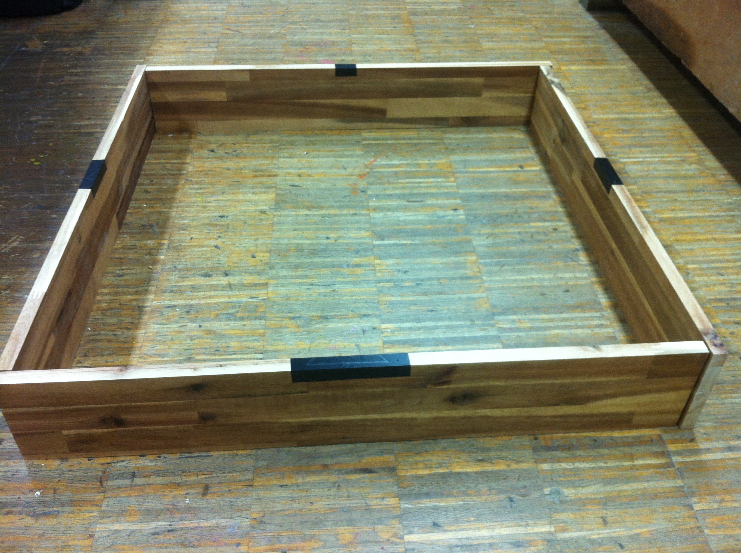
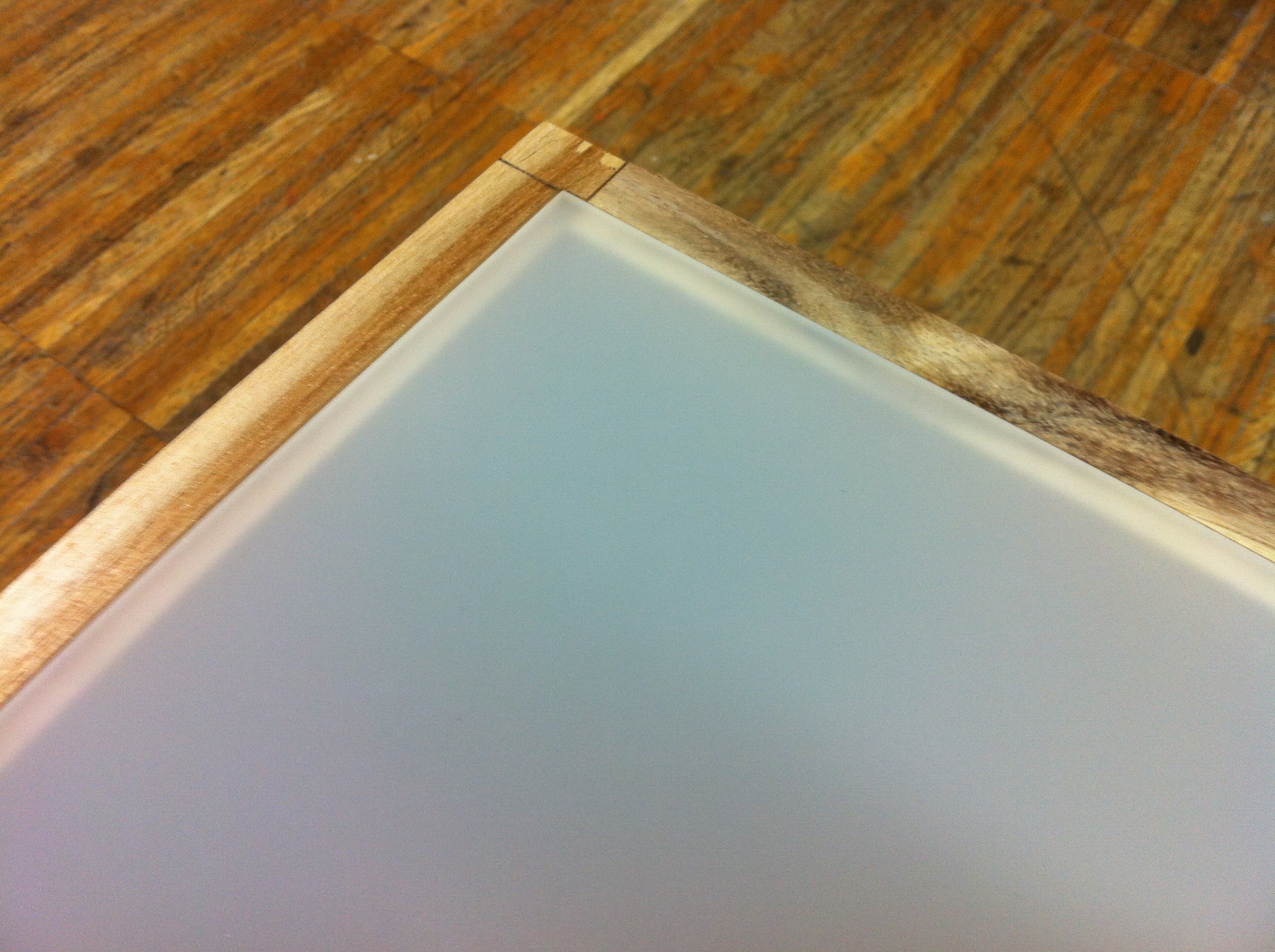
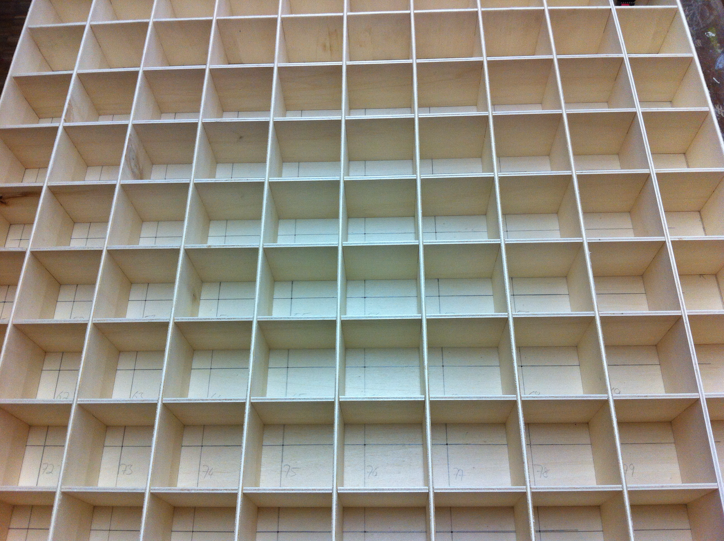
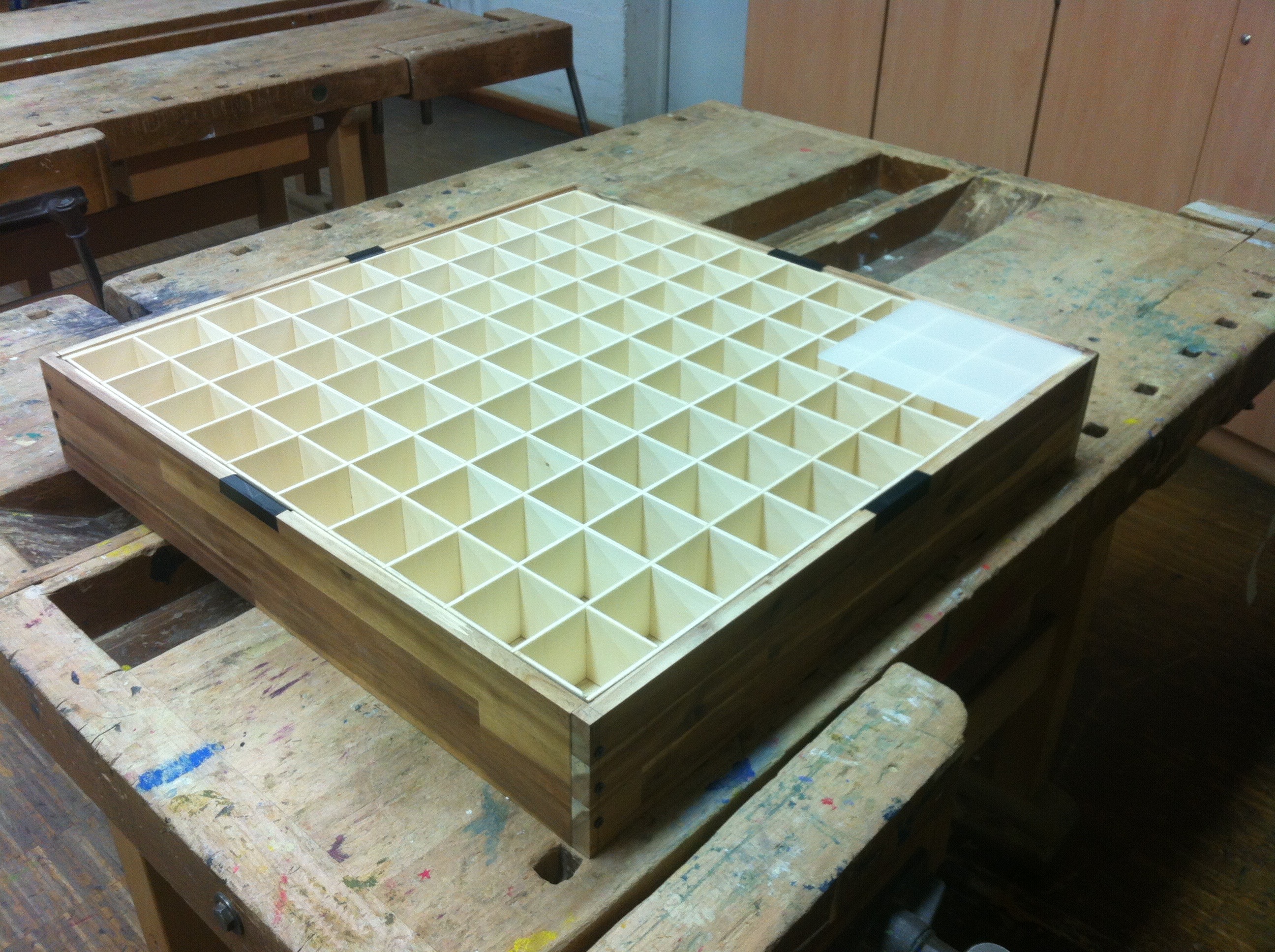
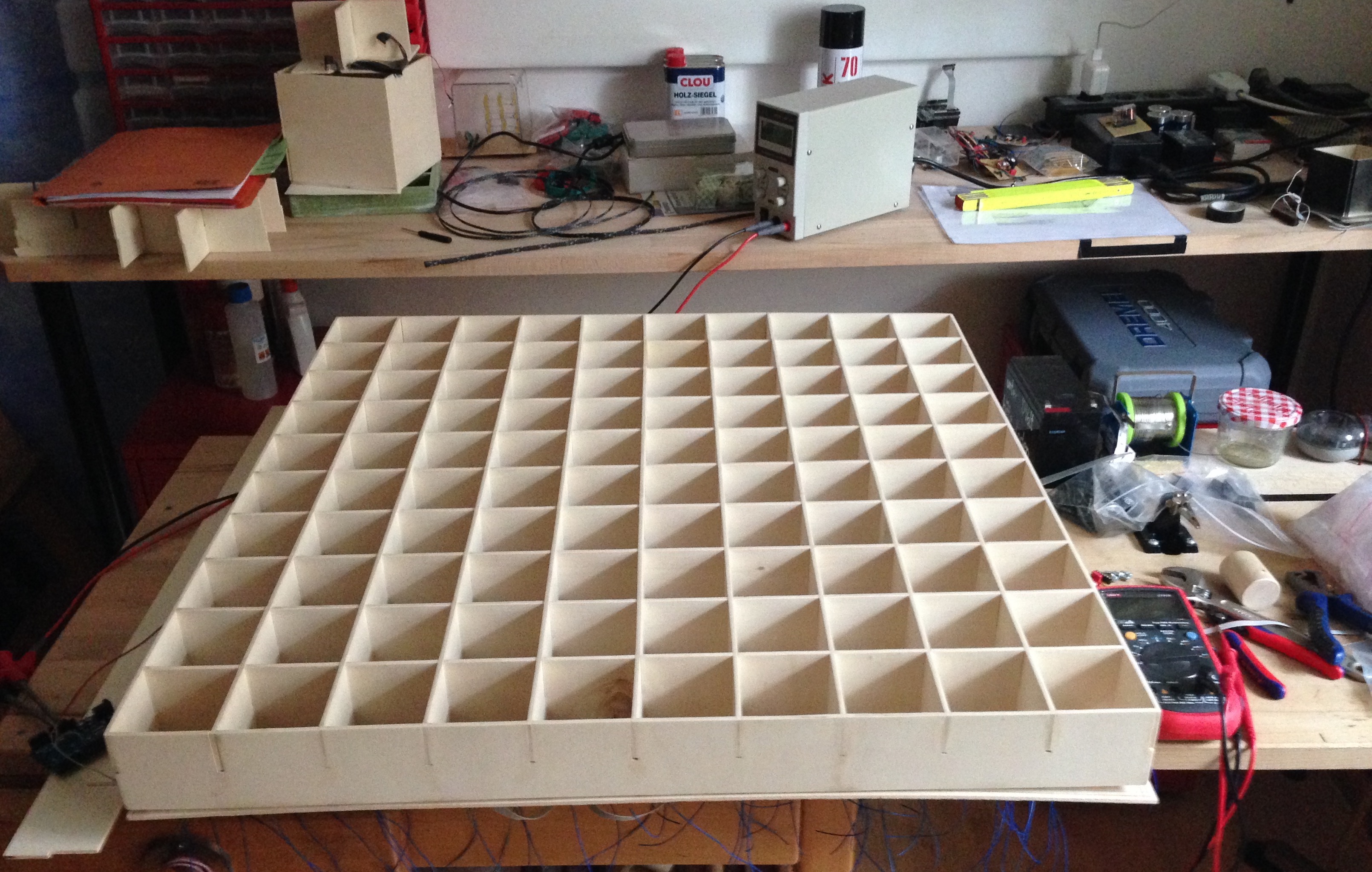
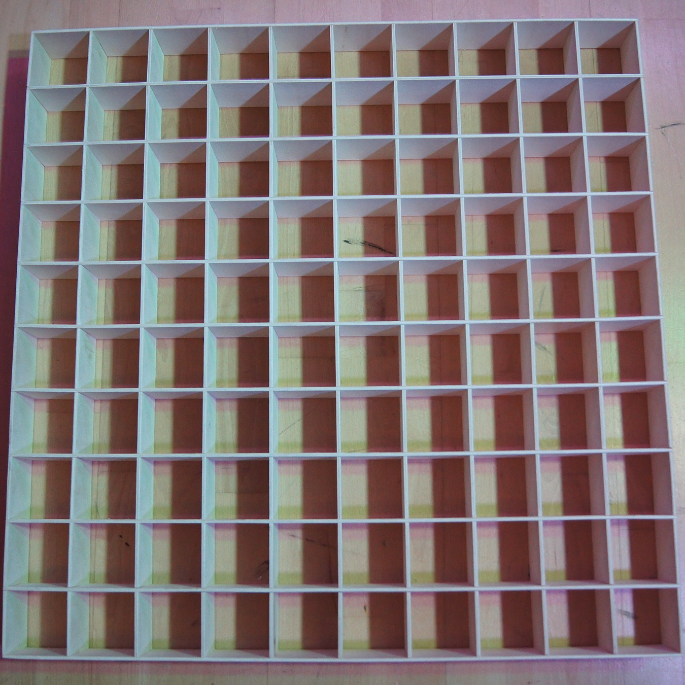
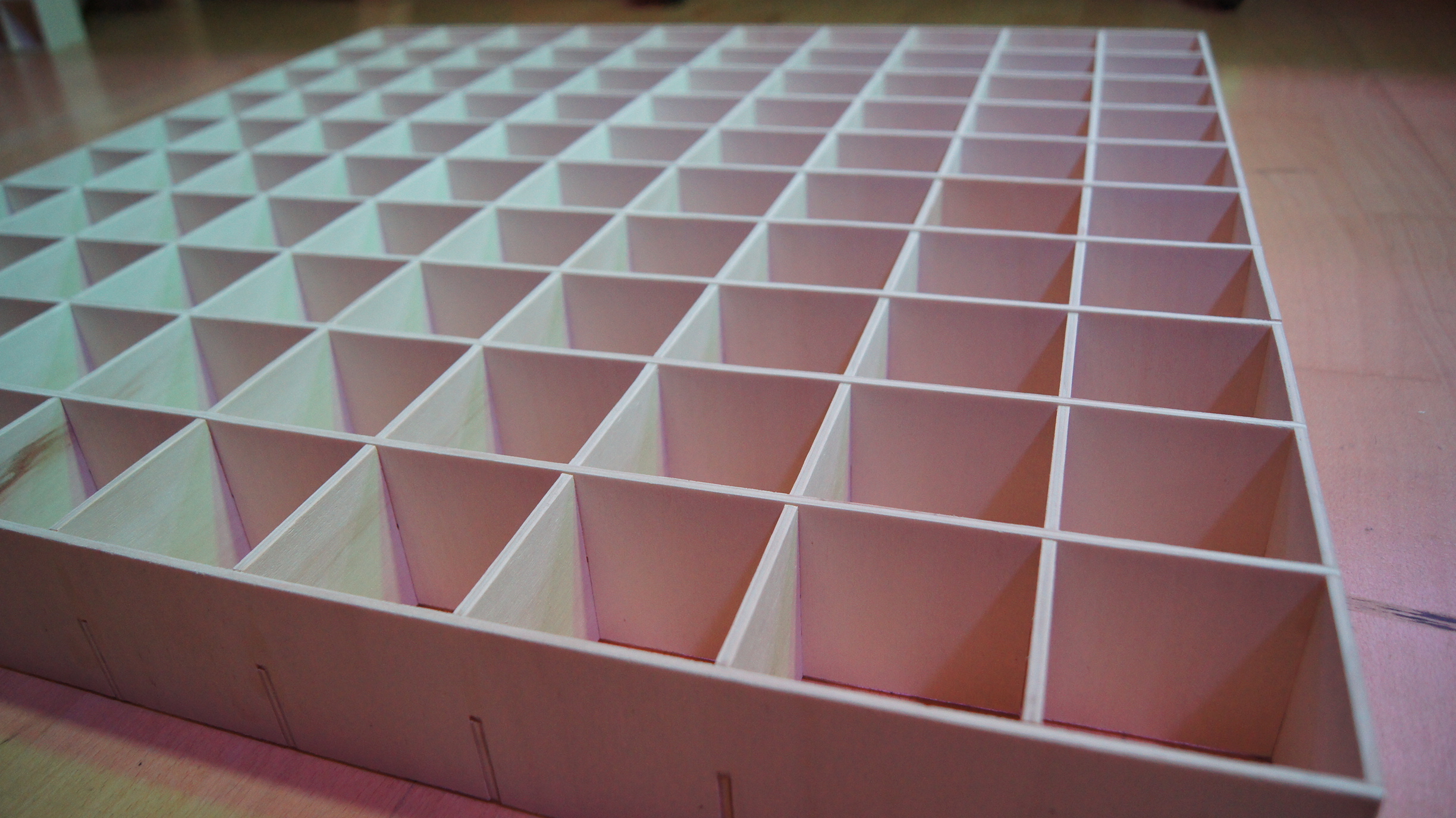
The wooden frame finally looked as shown. The floor was a 9mm thick plywood plate, the intermediate
level consisted of a 4mm Papple plywood plate as well as the 10x10 pixel grid. The whole thing was
finished with a frame made of 18mm acacia wood blockboard, which kept the whole thing in shape. In
the space between the floor and the intermediate level should come later the complete wiring of the
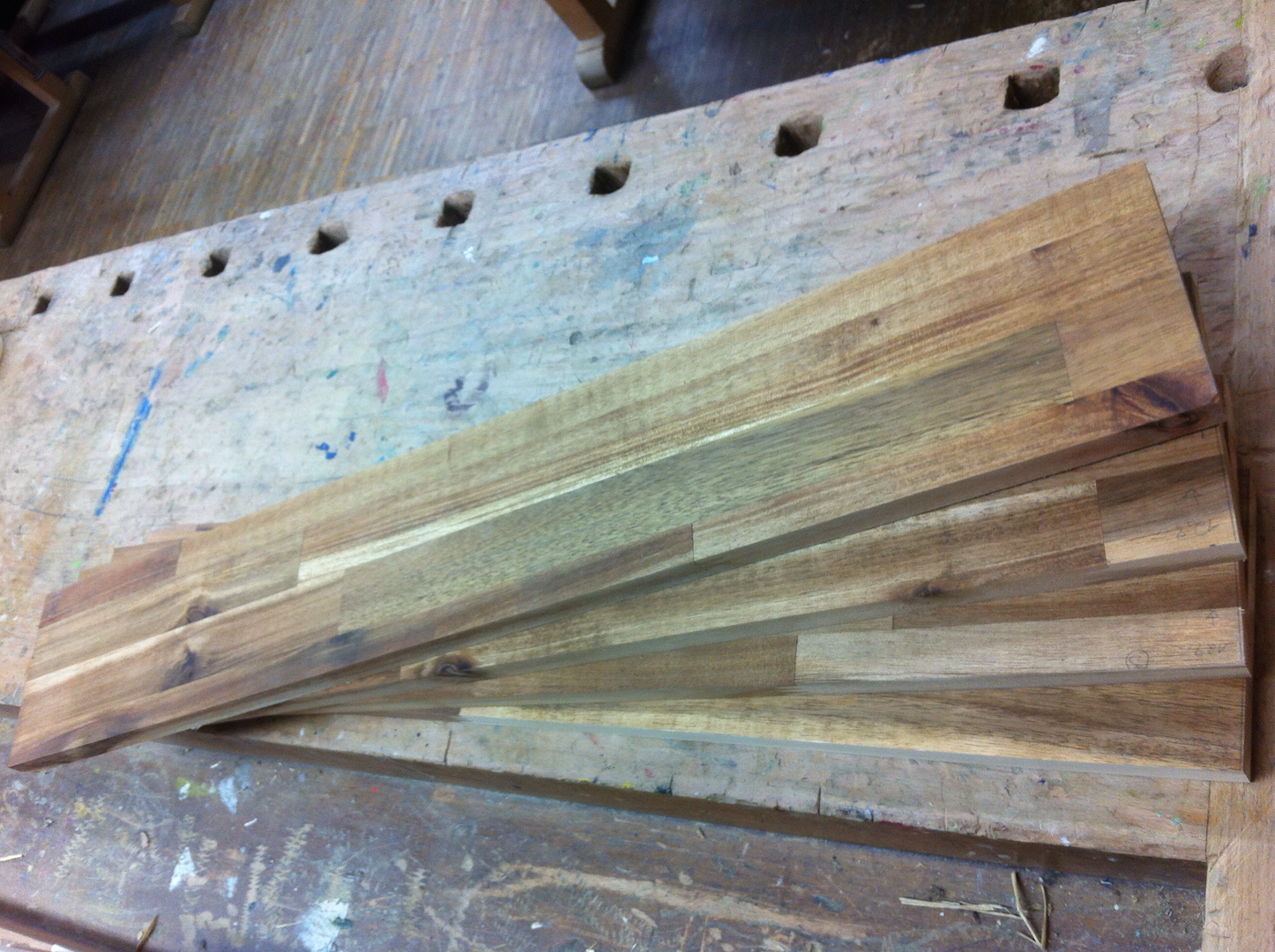
electronics and the control. For the grid I cut 22 plywood strips à 74,7cm x 7cm, which I milled in
all outside on both sides and then in distances of 7cm each up to half, so that I could put them
together then simply to a grid. The frame consisted of four equal parts, each of which was pushed to
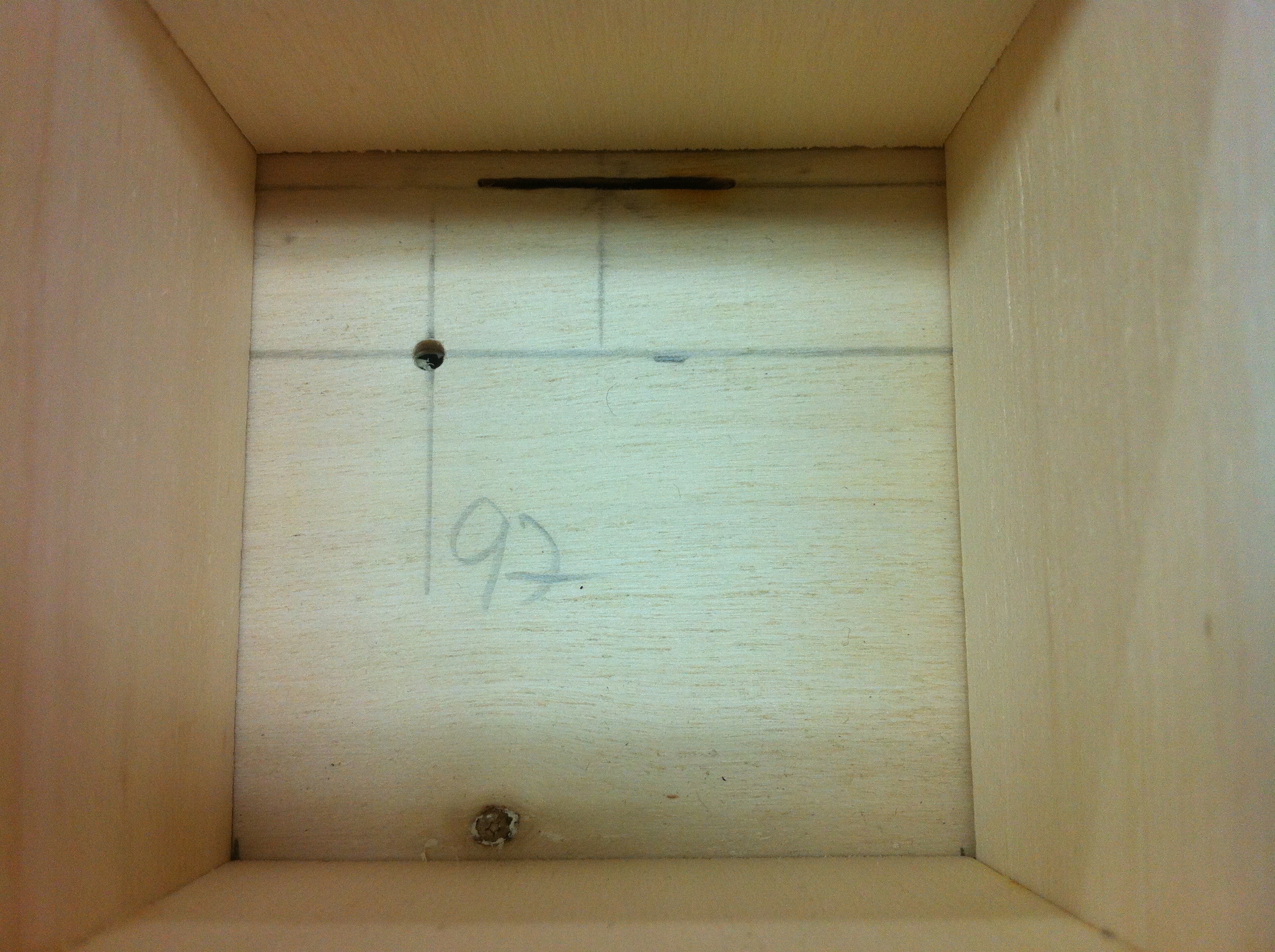
the right. In order to keep the intermediate level at the right height all around, I milled a slot
into the side walls at 4.9cm, in which the plywood plate should later be inserted. So that it did
not hang through in the middle, it got small spacers to the ground. The base plate was screwed to
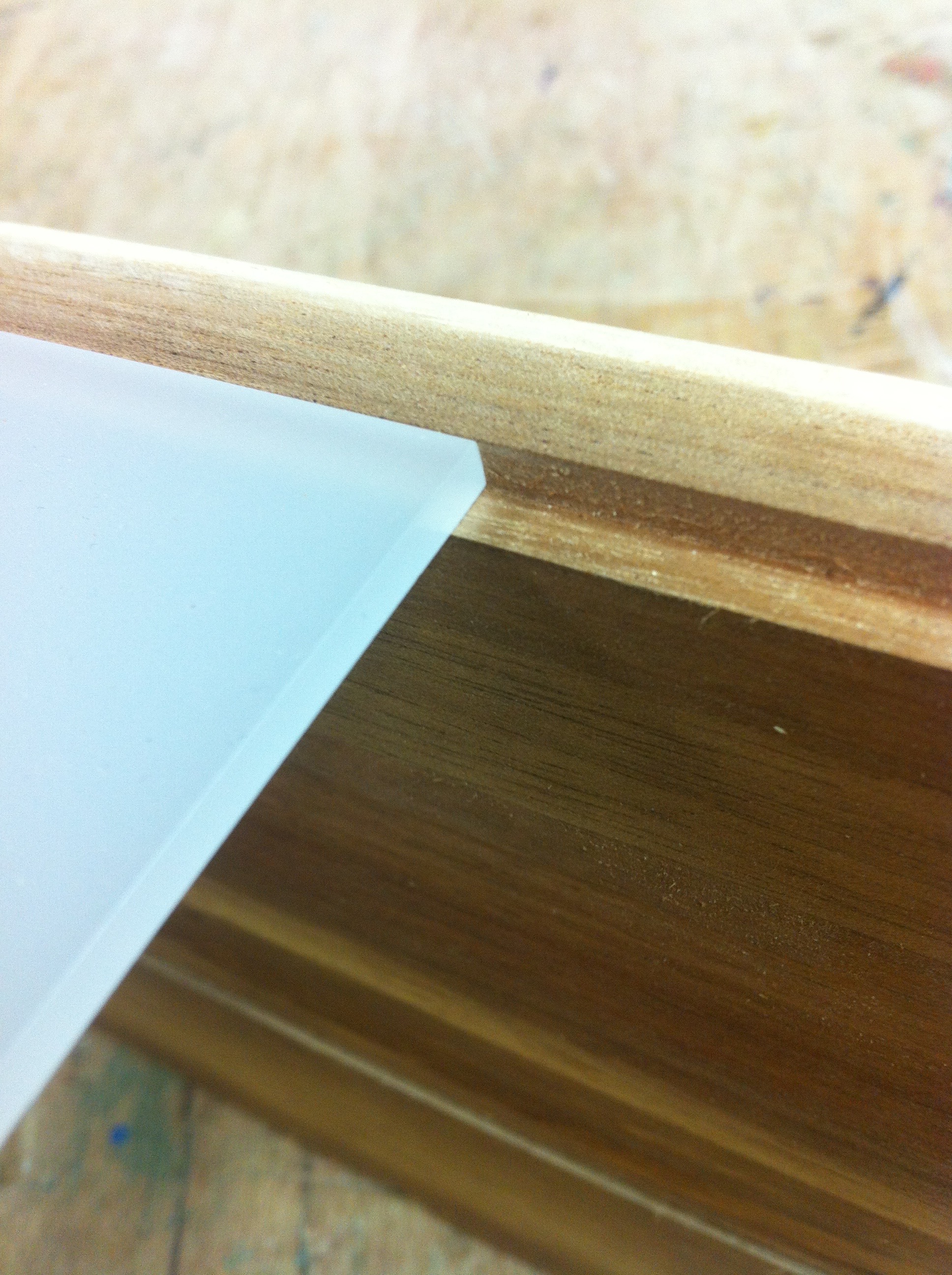
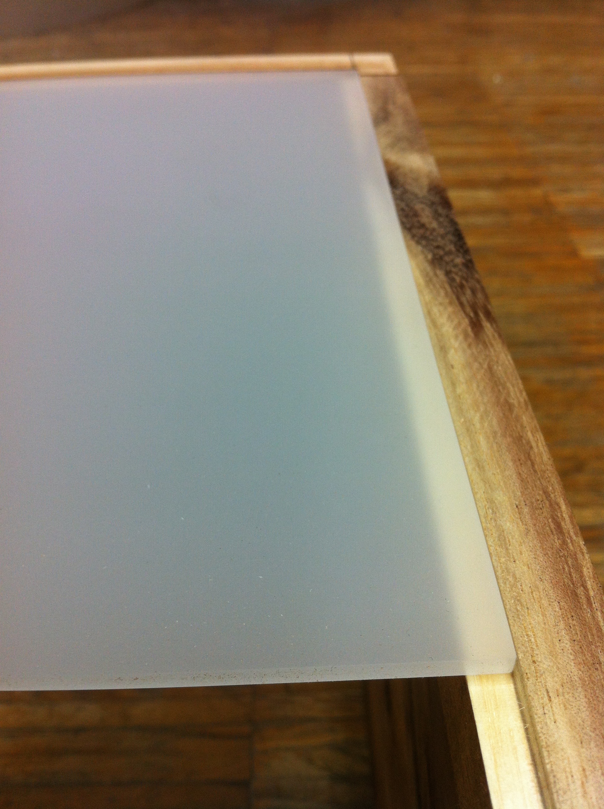
the frame and the grid should be in the frame without any extra fastening. On top of it there was
only the 3mm thick Plexiglas pane, which was also flush mounted by a small milling edge.
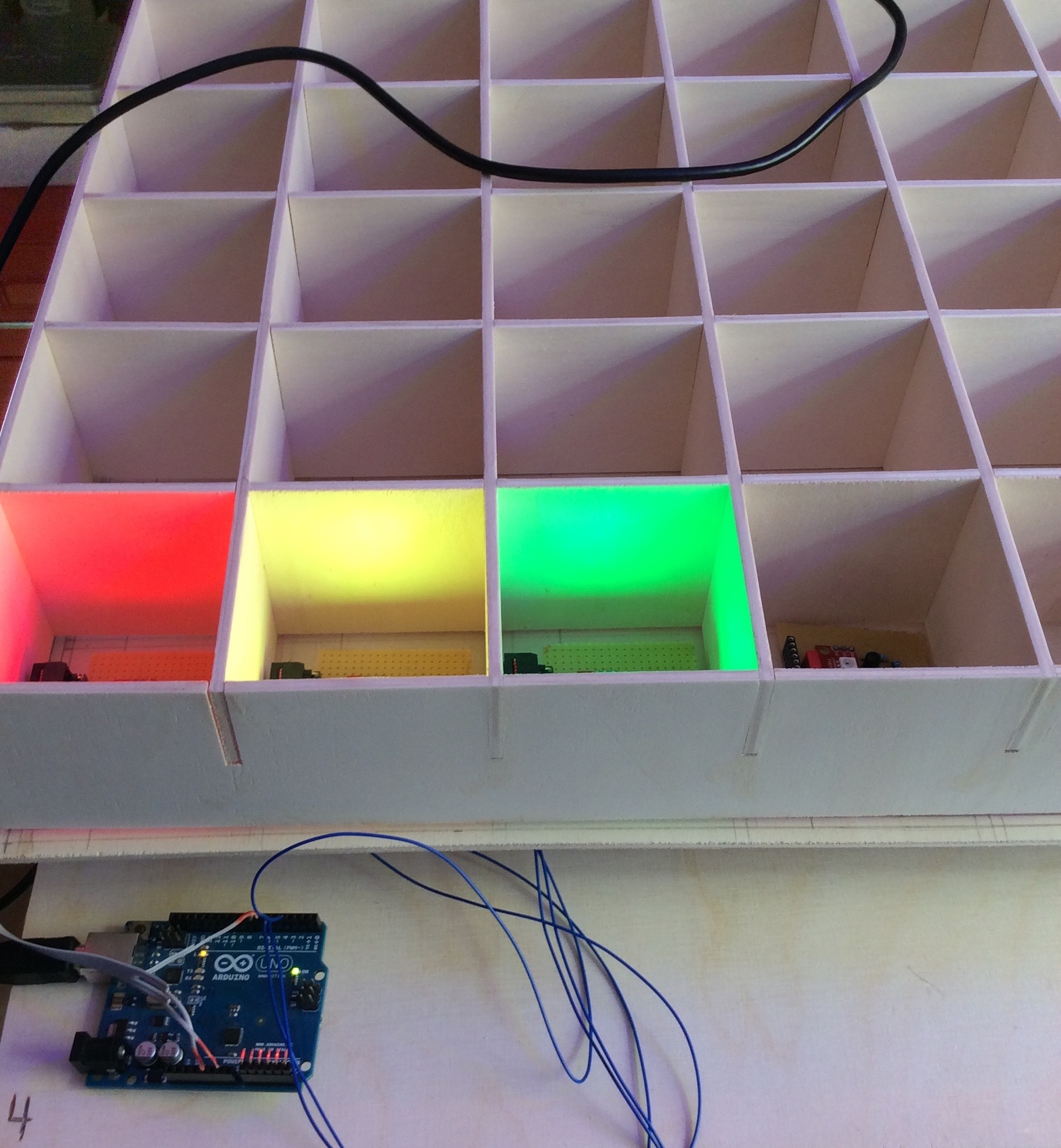
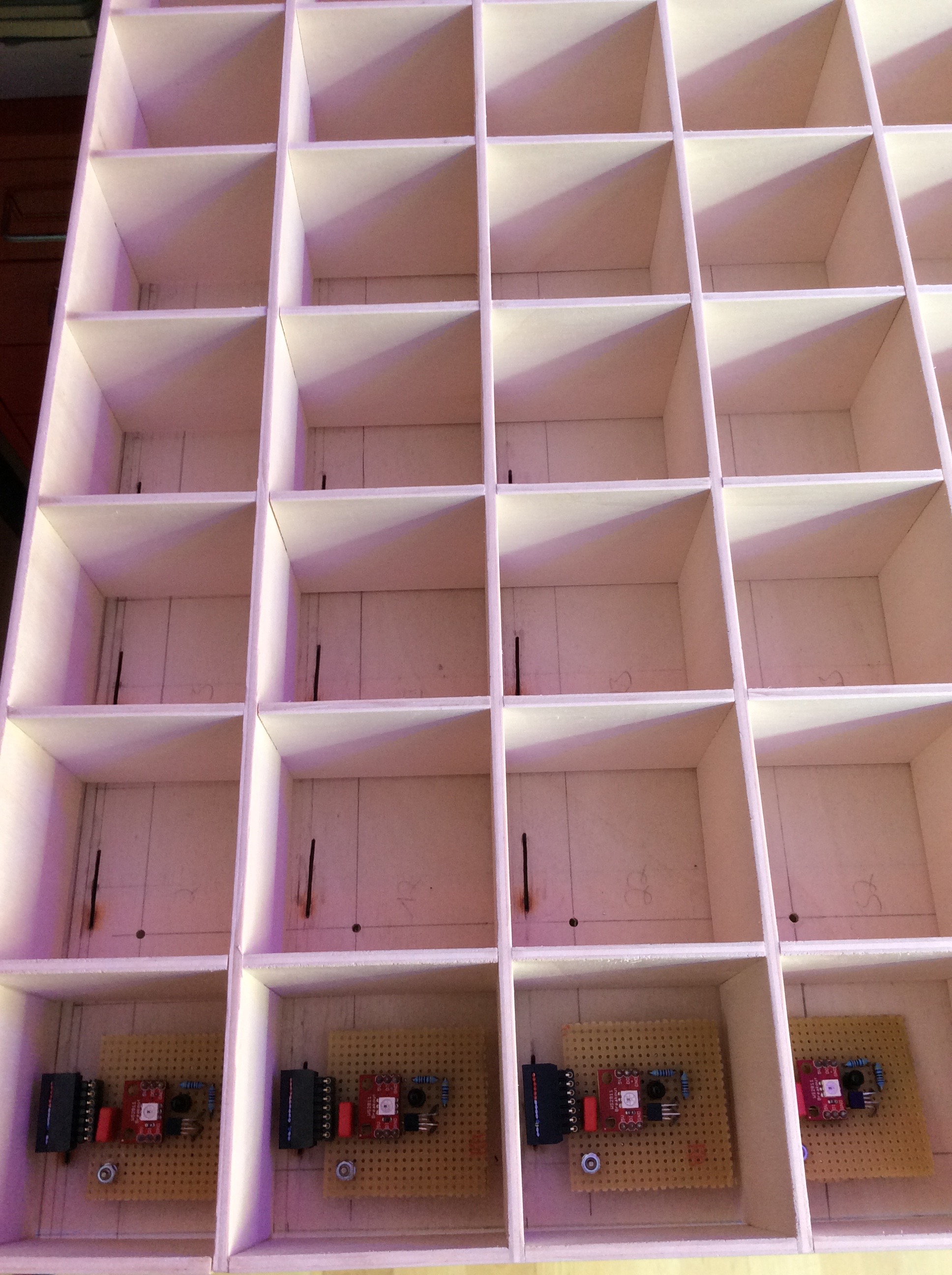
Since I was still waiting for the remaining orders and the construction of the 100 PCBs would take a
while, I started a small test with the PCBs from my 2x2 pixel prototype and the finished 10x10 pixel
table frame. I wanted to get an impression of what it would look like at the end, even if it wasn't
really the case with 4 pixels! But I noticed something else not very desirable, namely the touch
didn't work as I wanted it to... So if I started the sample code while the Plexiglas pane was on the
pixel grid, the pixels would glow as desired. But as soon as I drove my hand over it, and the pixels
were supposed to go out only as long as they were covered, they stayed off! The error wasn't due to
the code either, because if I tried it without Plexiglas, it worked as it should... After several
days of despair I came across the error and it was more than shockingly simple and yet very hard to
find. I had assembled my 4 pixel prototype with the plywood somehow and had (of course) not paid
attention to the grain of the wood! With my 10x10 pixel grid this was sometimes the same and
sometimes perpendicular to the one in my prototype... That meant that I was allowed to rebuild the
grid again and this time with the grain identical to the one in the prototype (with the grain
running from bottom to top and not across, otherwise the reflections of the infrared light would
have gone too strongly in all directions and thus been falsified!) With the new grid everything
worked as it should and until that was the case, my remaining orders had also arrived:)
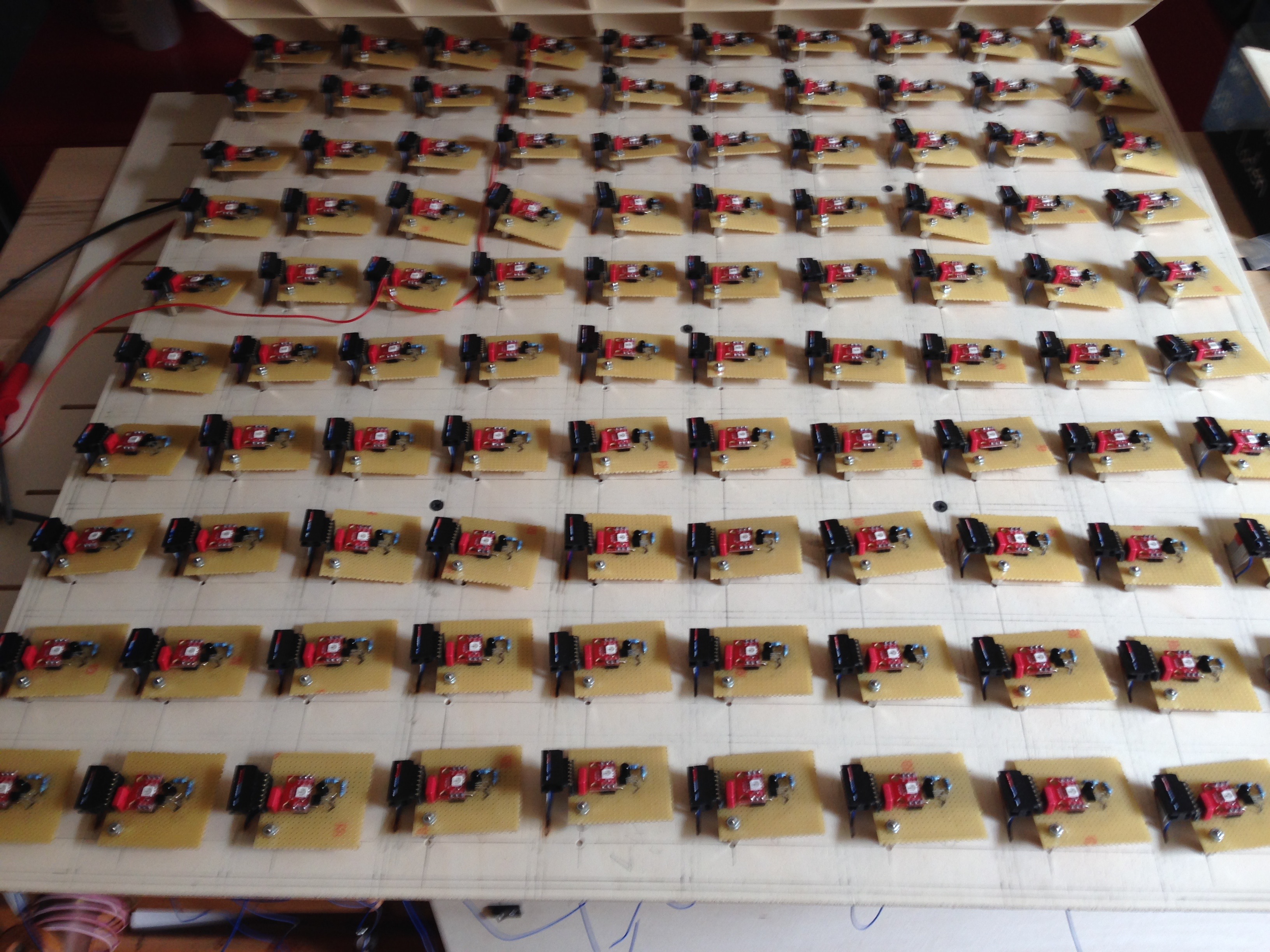
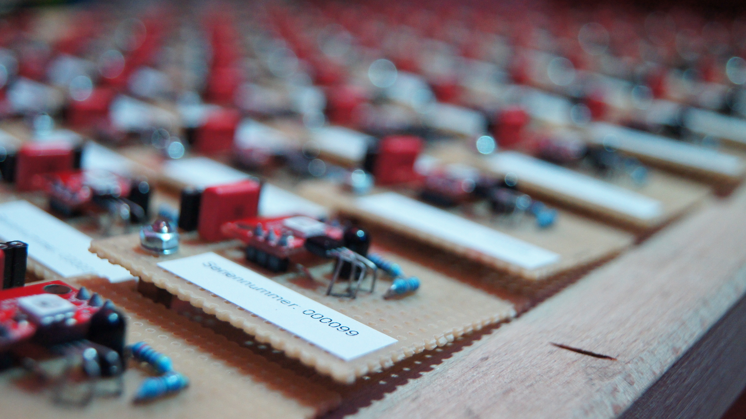
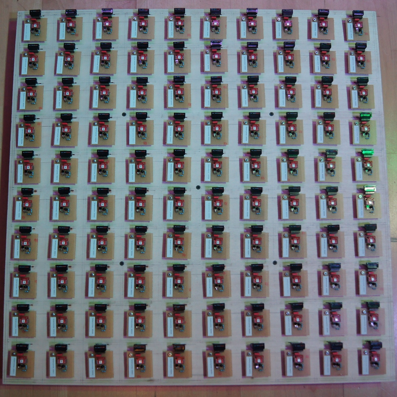
Since now all components had arrived, from now on it was only soldering, soldering and soldering
again! Because it will take a while until you have soldered and tested such a lot of single boards
by hand. But the experience was worth it in any case and one becomes better with the time also with
the soldering;) How the whole thing looked at the end can be seen on the pictures.
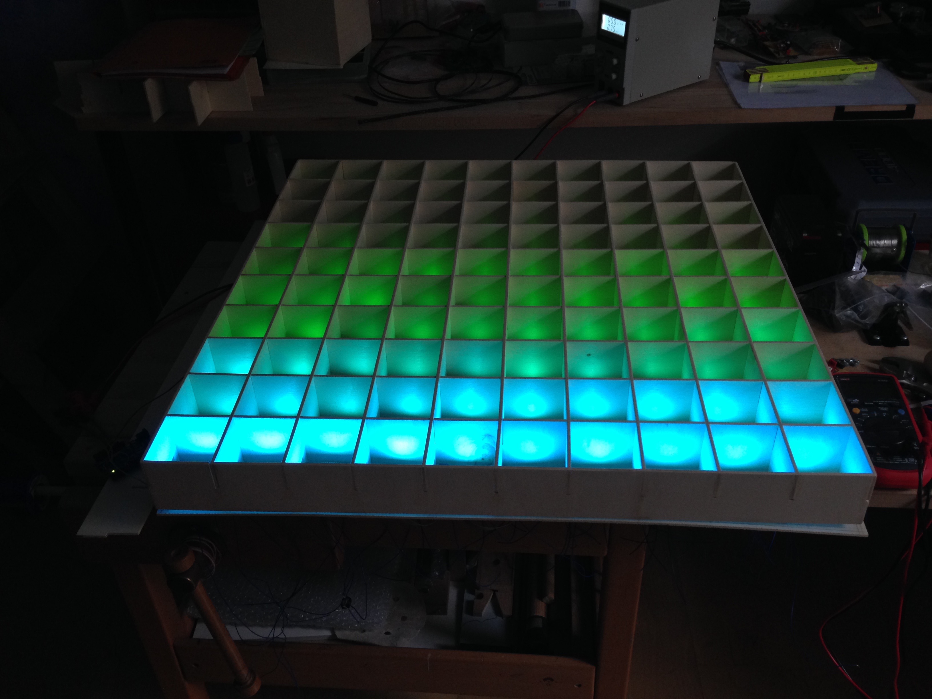
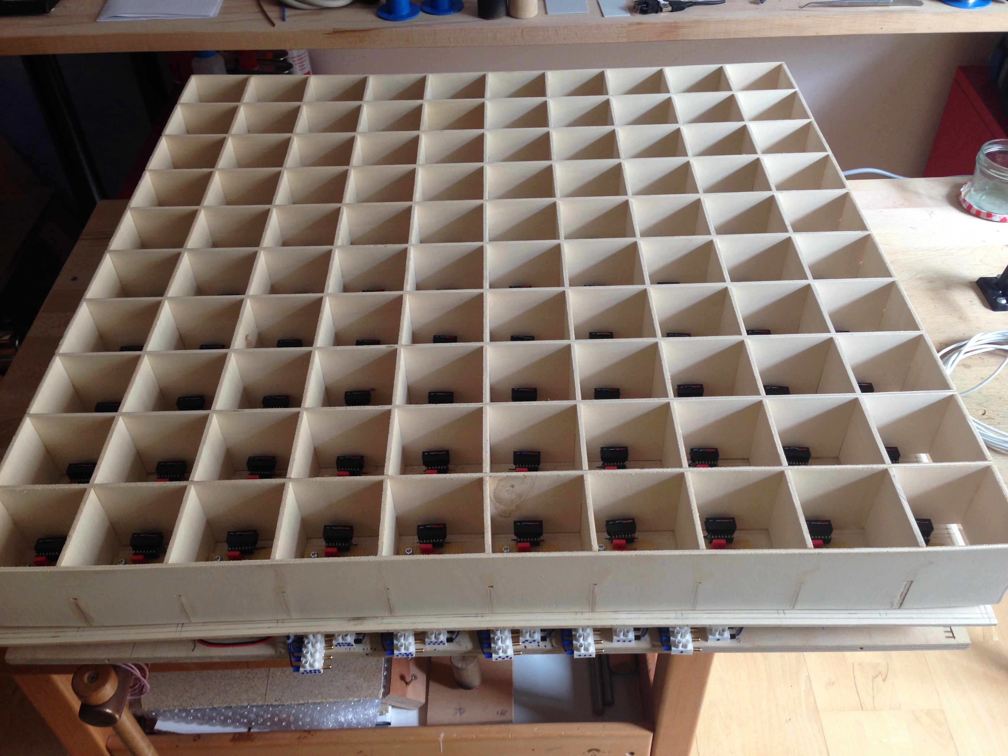
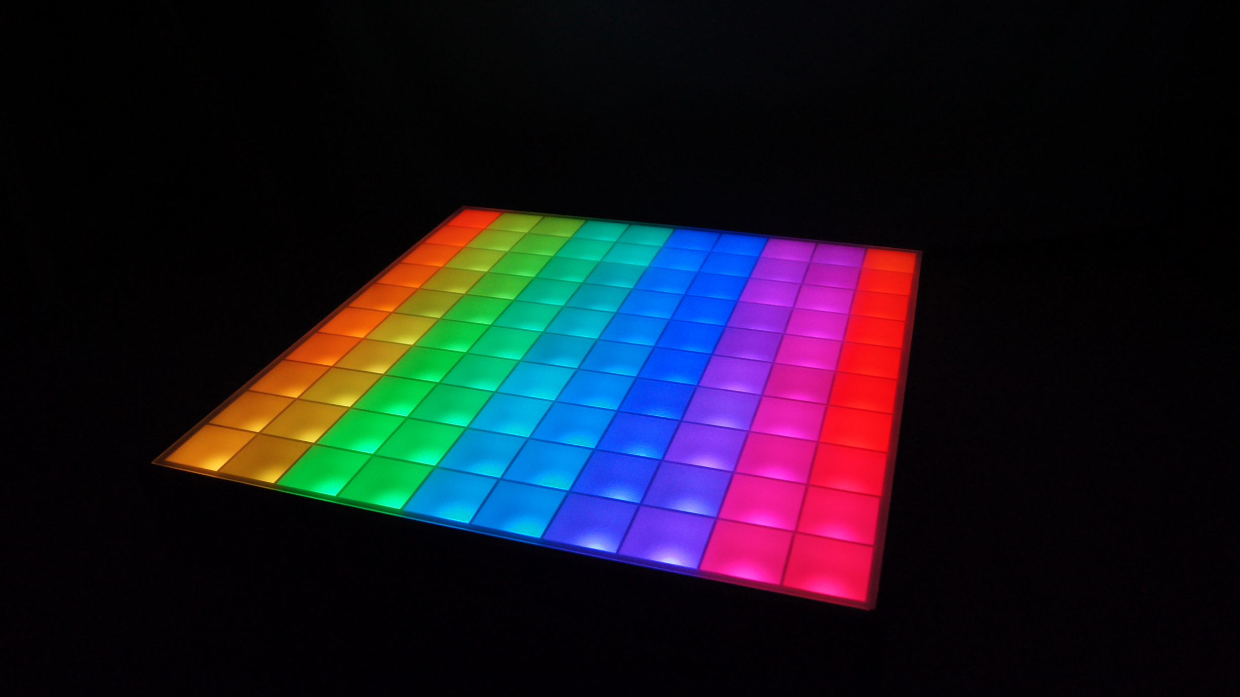
And what do you do next when you have finished soldering all 100 boards? Of course, test it! So I
prepared the complete wiring for the pixels by cutting the ribbon cables to the length from one
pixel compartment to the next and then connecting them with the corresponding ribbon cable plugs.
Now I connected all boards at their intended places and connected the data input of the first board
with the Arduino Uno. Then I had to supply the boards with power, which I did with an extra 5V power
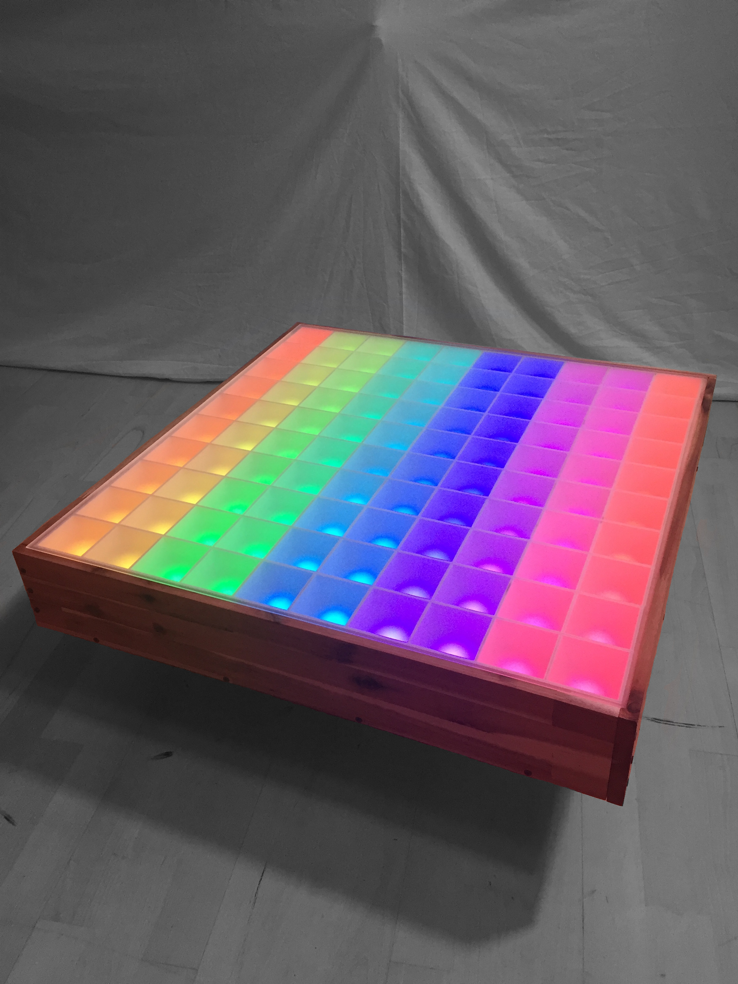
supply with sufficient power. Now for the first time I was able to put all 100 pixels into operation
at the same time and see what it looks like in the pixel grid! Unfortunately this was not as
impressive as I had hoped (see pictures), because already after 1-2 rows the current was not enough
for the remaining LED's... So I helped again by spitting 5V from the power supply into every 2nd
row. After that everything went as expected.
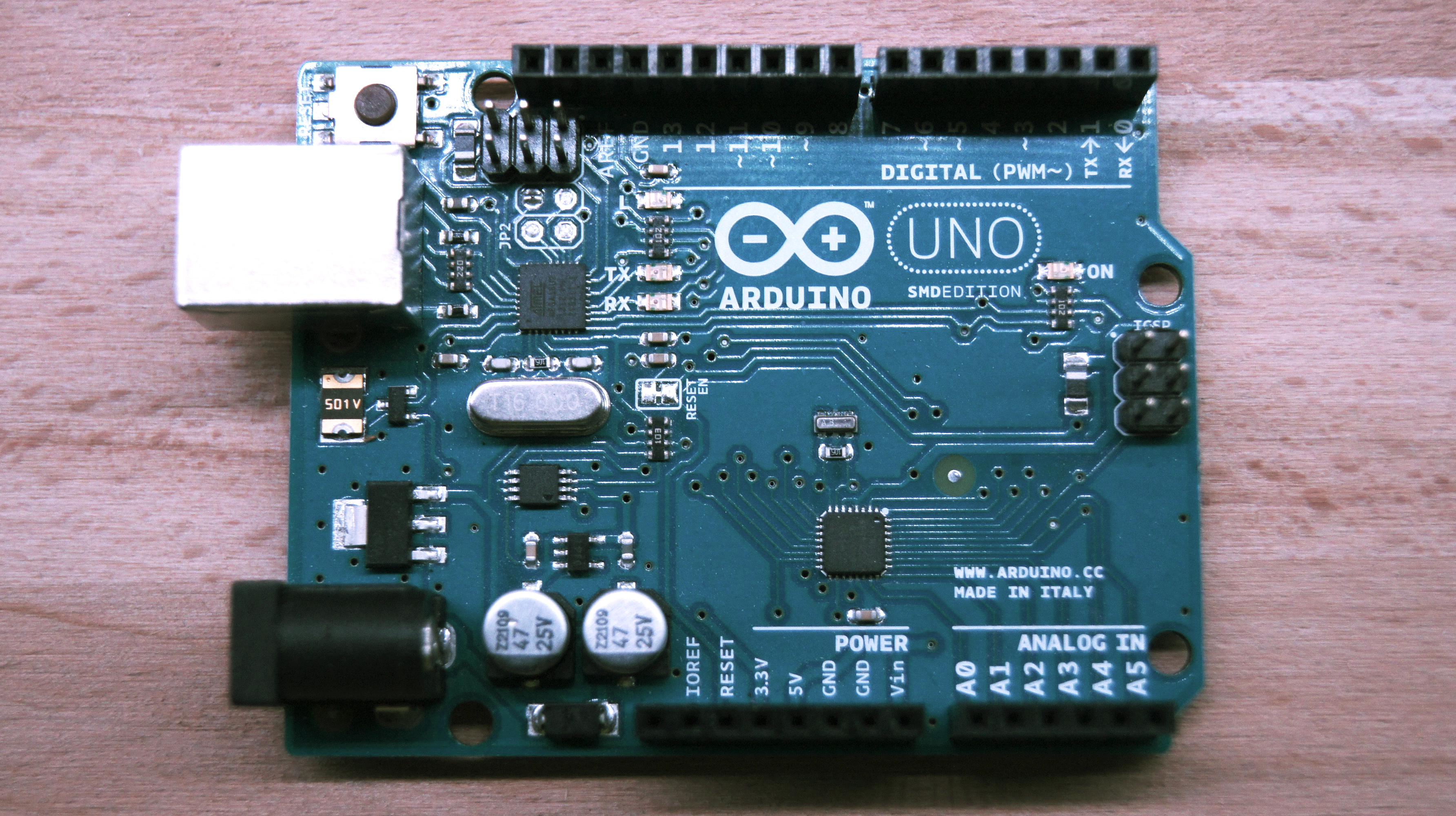
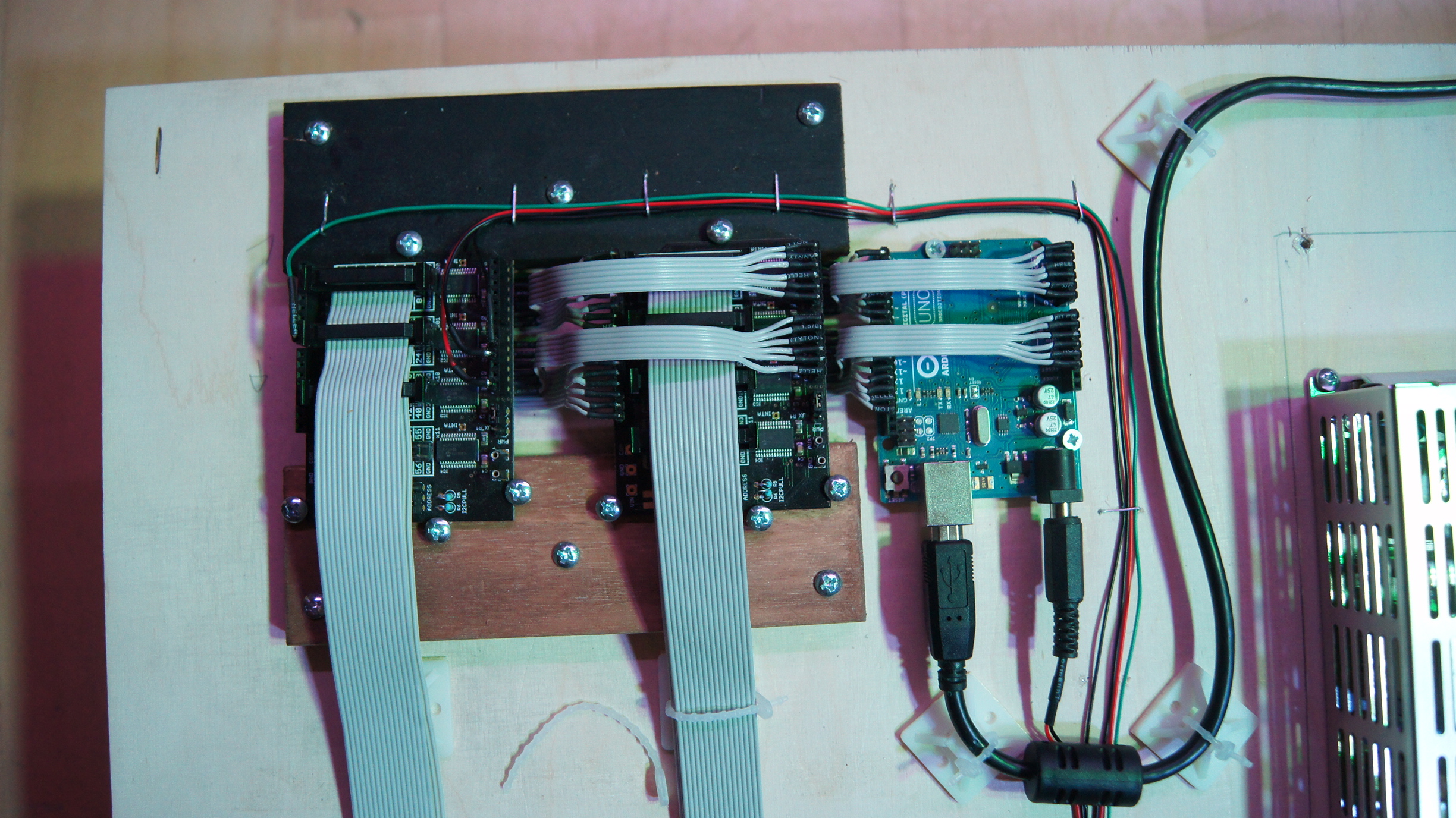
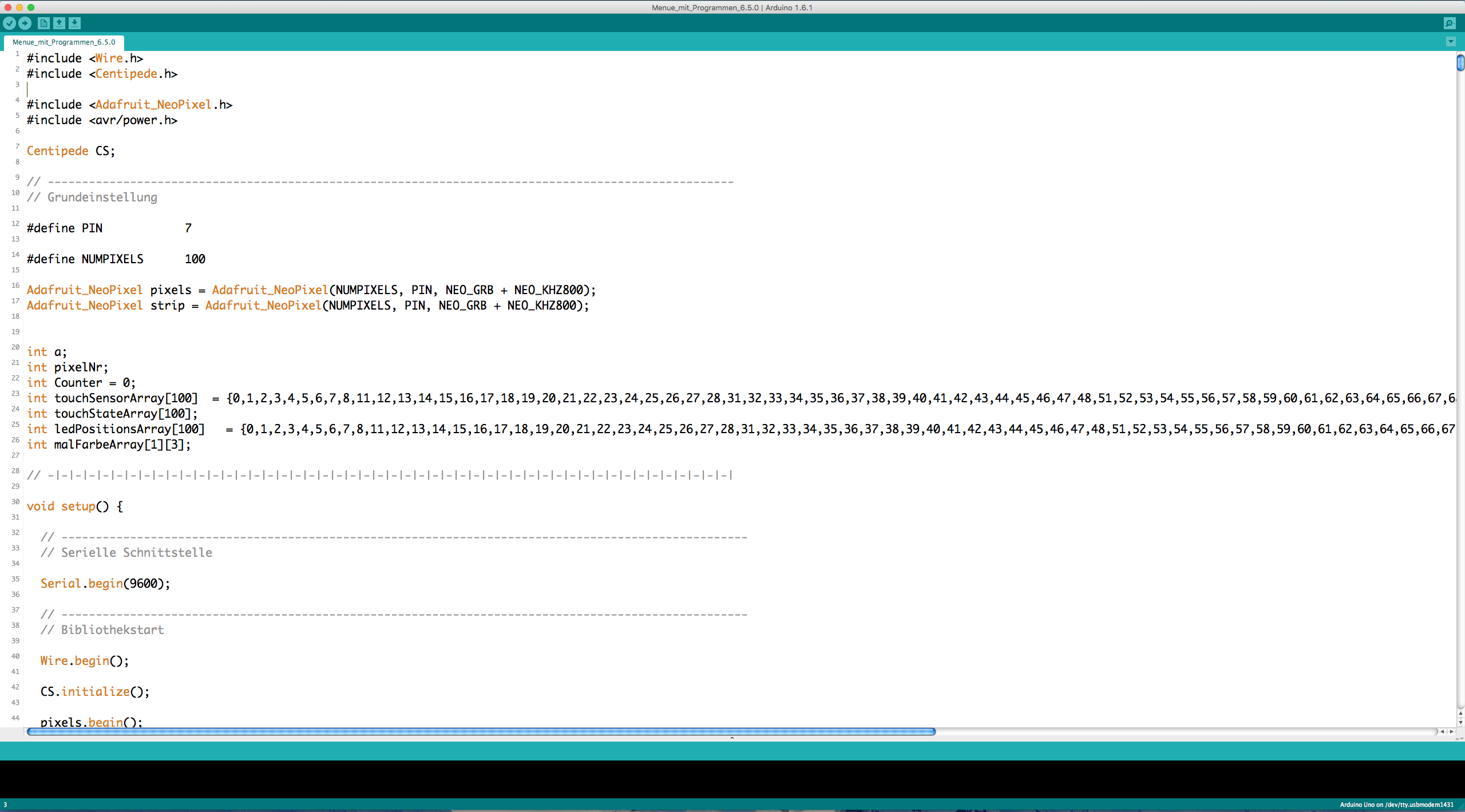
The next question is, of course, how do I control the whole thing and how do I get all 100 digital
output signals from the IR sensors correctly read and processed? Generally I wanted to control the
table with the Arduino Uno, but for the large number of digital inputs I had to think
about something else, because it has only 14 digital inputs... Here I used the so called Centipede Shields from Macetech, which are pretty easy to use pin
extension boards for the Arduino. With these I got up to 64 digital pins per board and therefore
also 64 digital inputs. But since I needed 100 inputs, I simply needed two of these expansion
boards, which can be expanded just as easily! In the Arduino IDE you only have to include an extra
library to use the boards, and work with slightly different commands, otherwise everything is the
same as with the Arduino Uno!

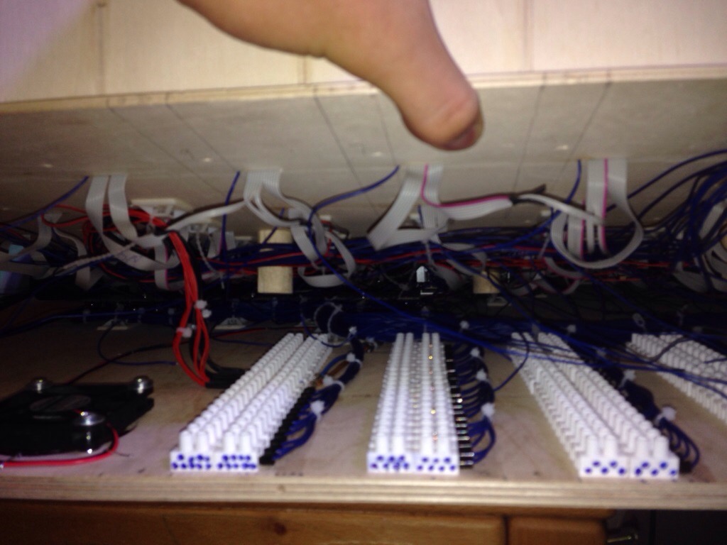
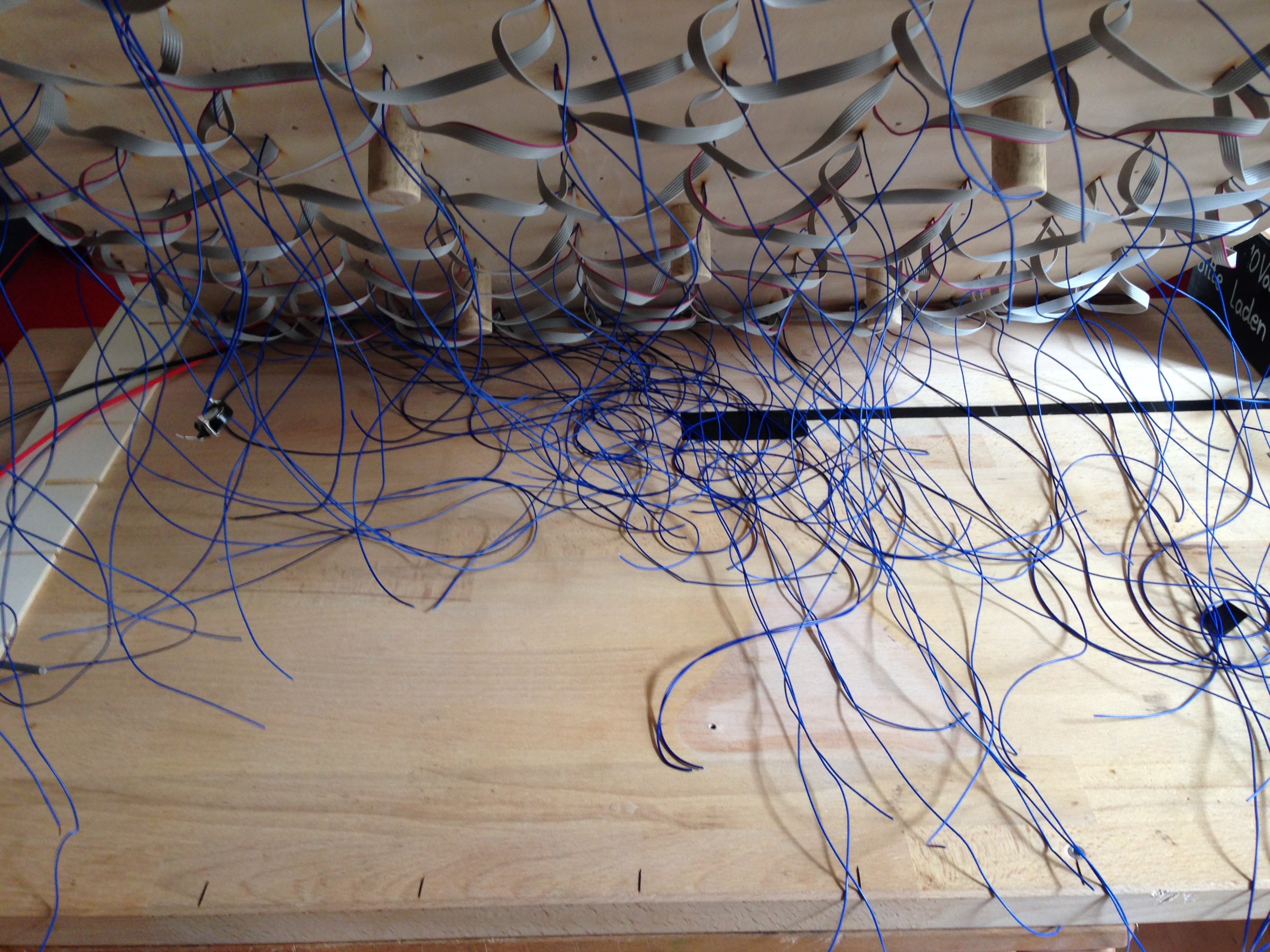
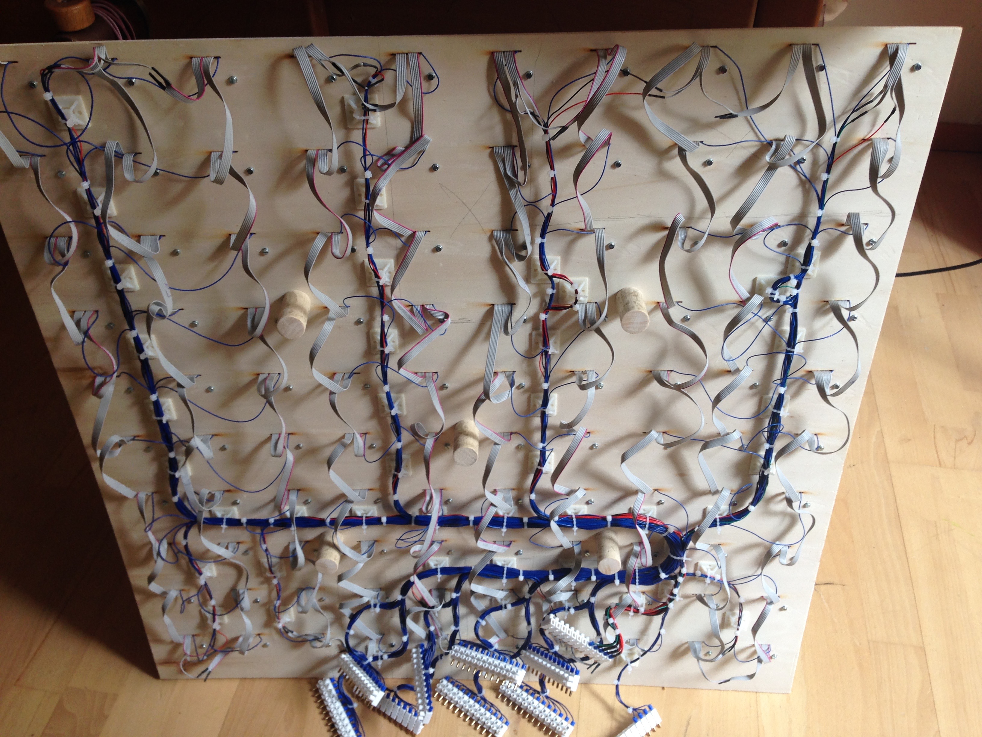
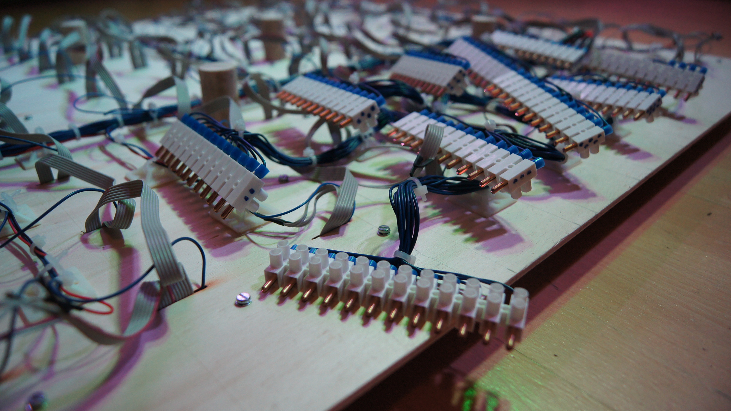
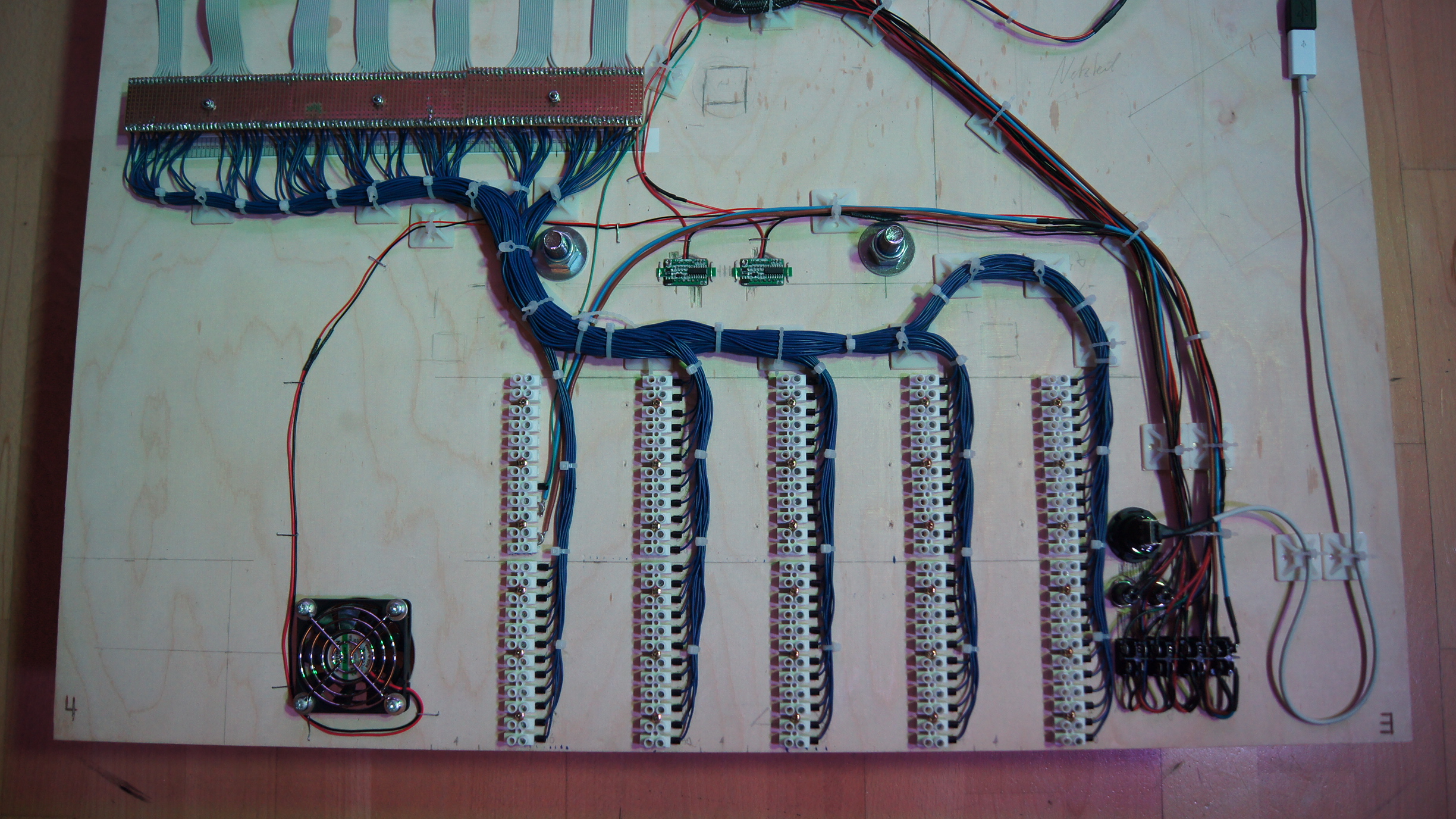
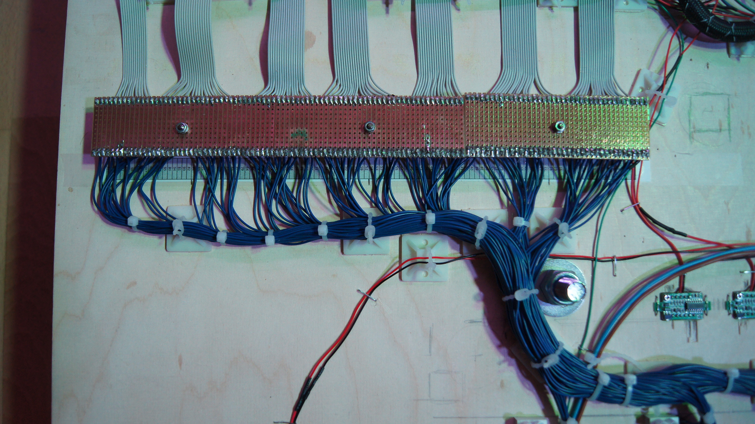
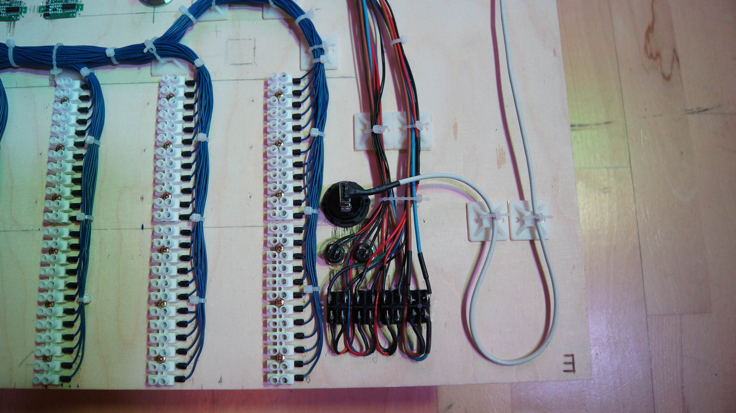
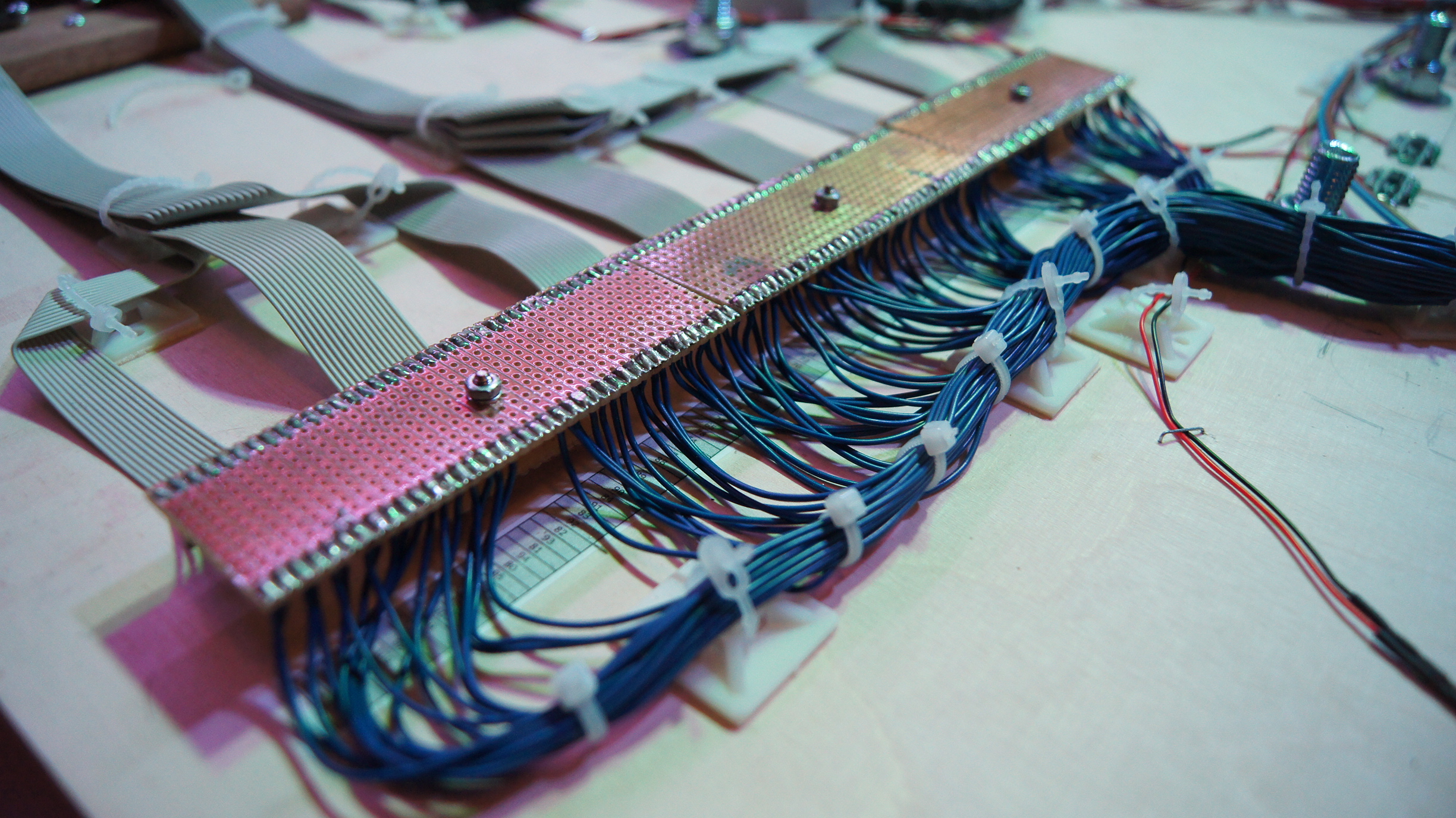
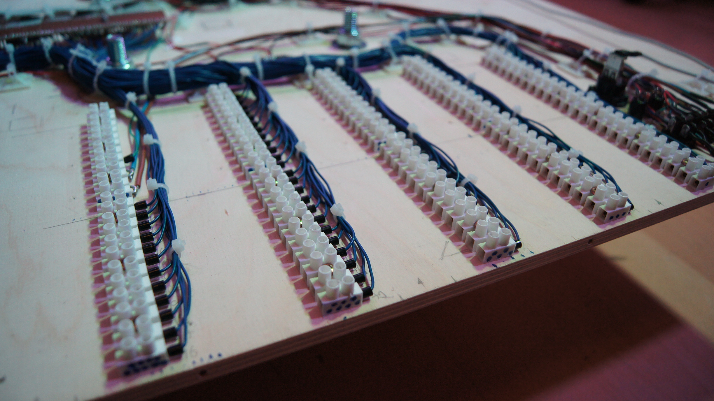
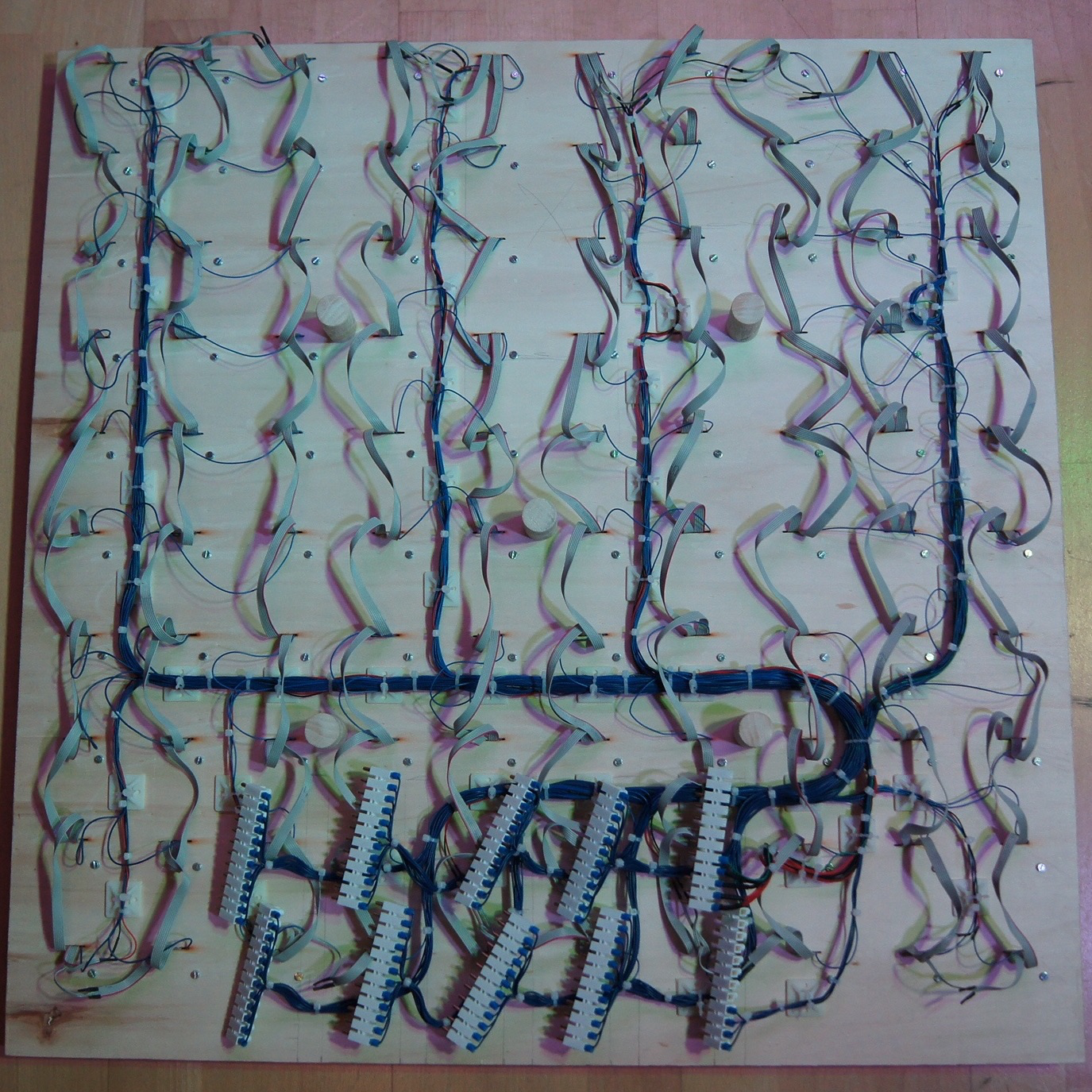
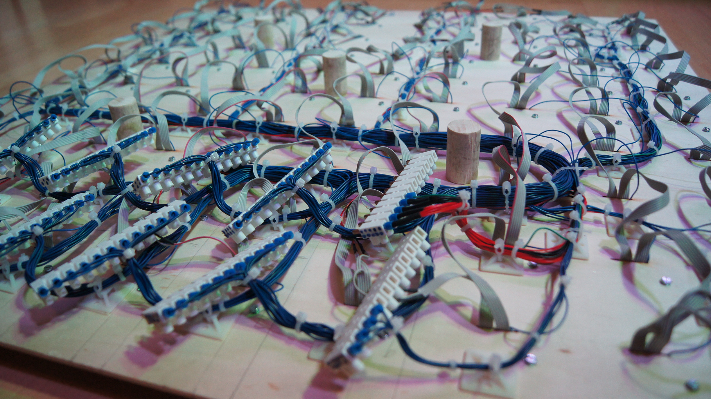
Now came what was probably the most nerve-wracking work, the wiring! I wanted to make this as clear
and comprehensible as possible, so that possible later defects could easily be located again. In
addition, I wanted to design the connections to the control electronics in the level below so that I
could take the table apart again later in order to be able to make changes to it. For this I used
pluggable lyster terminals as you can see on the pictures. The data pin and the power supply for the
printed circuit boards were also connected from the power supply via the lyser terminals.

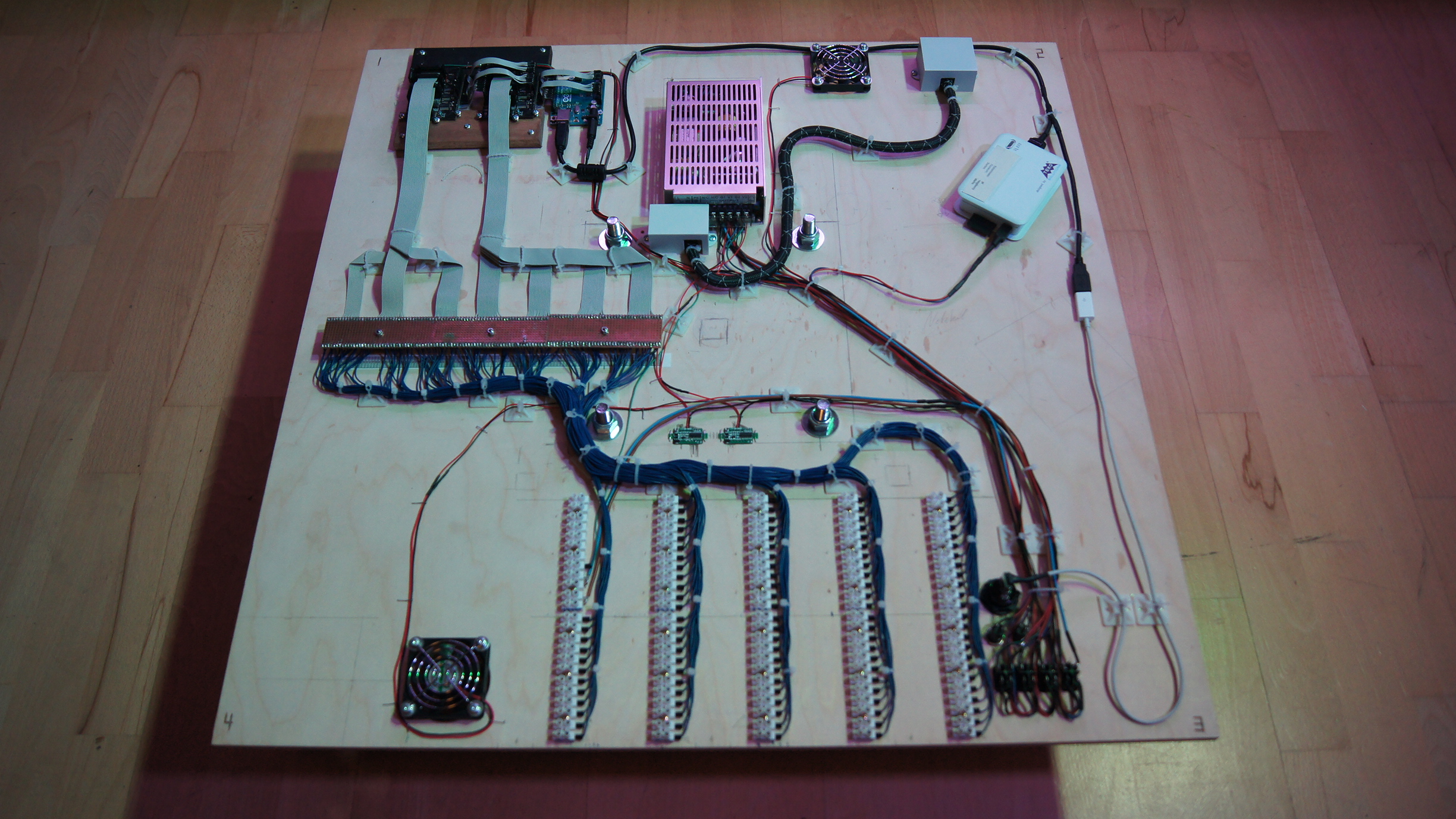
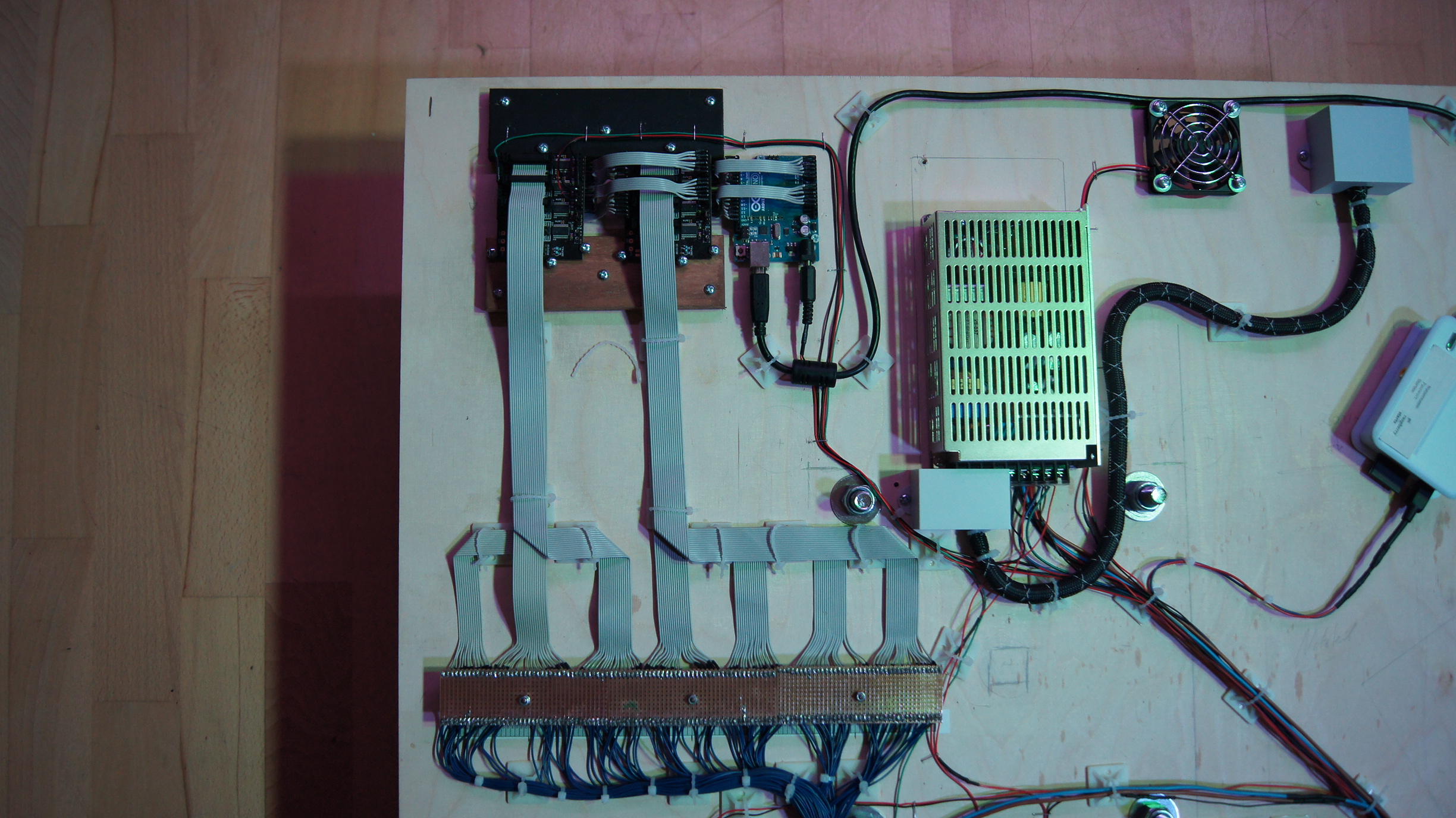
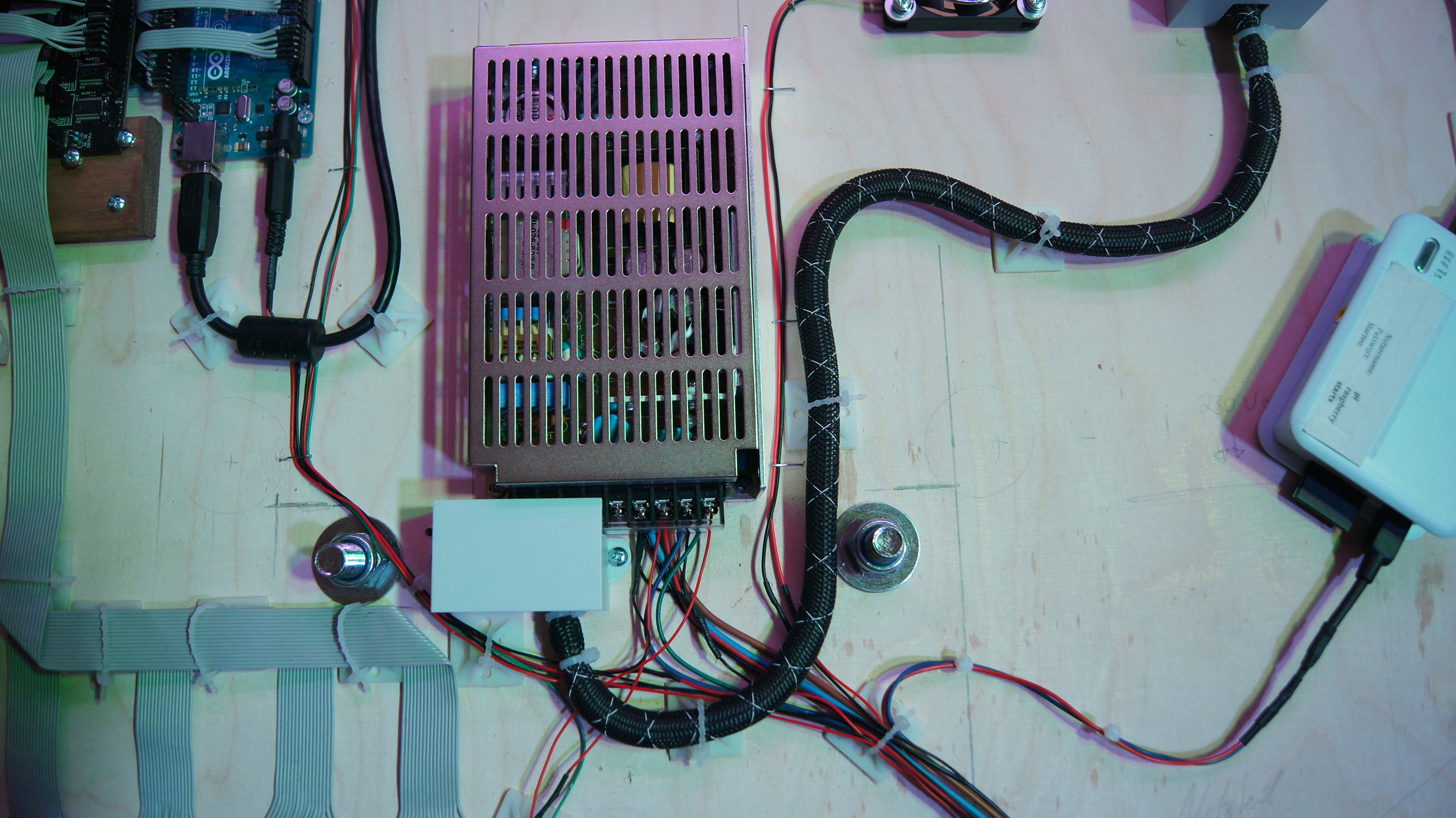
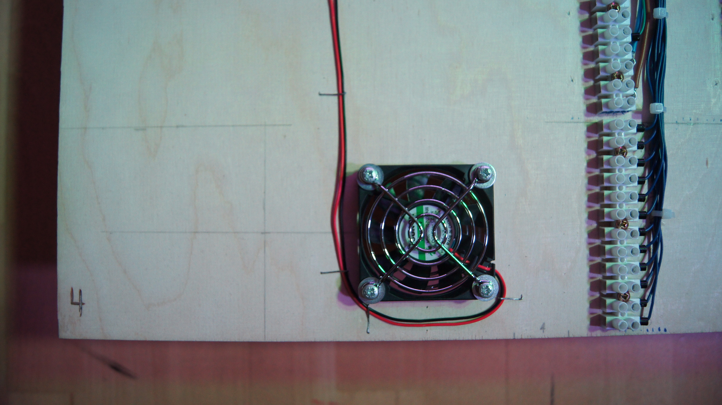
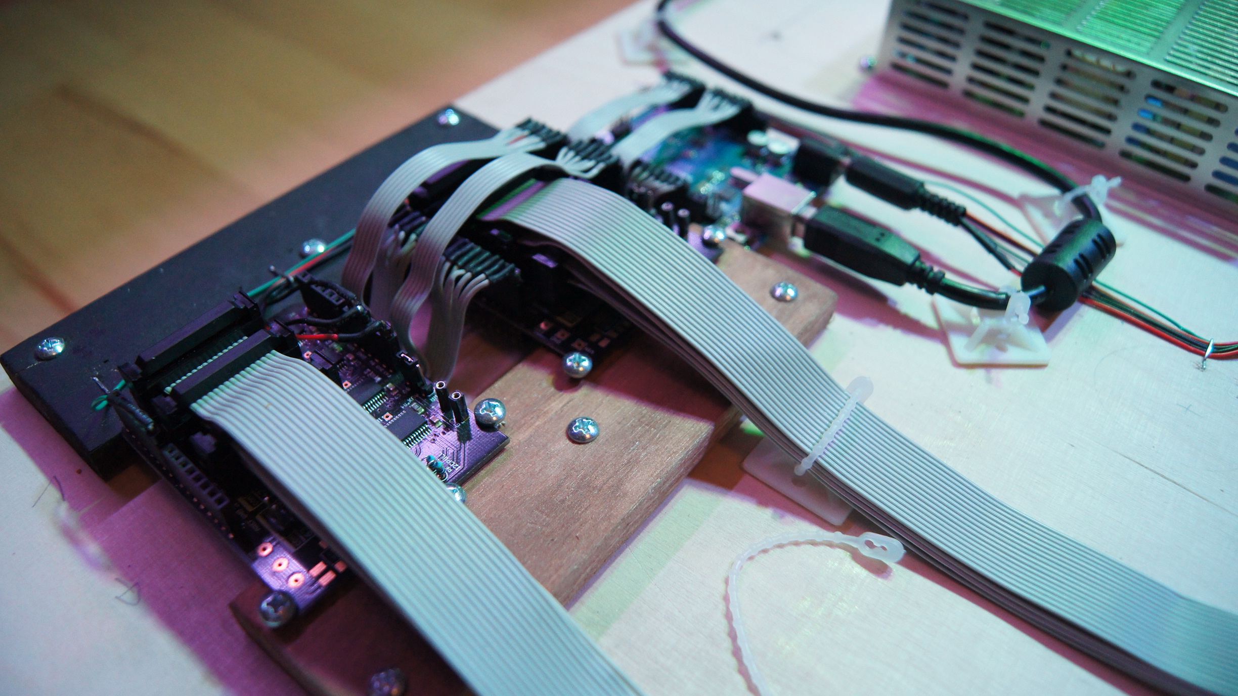
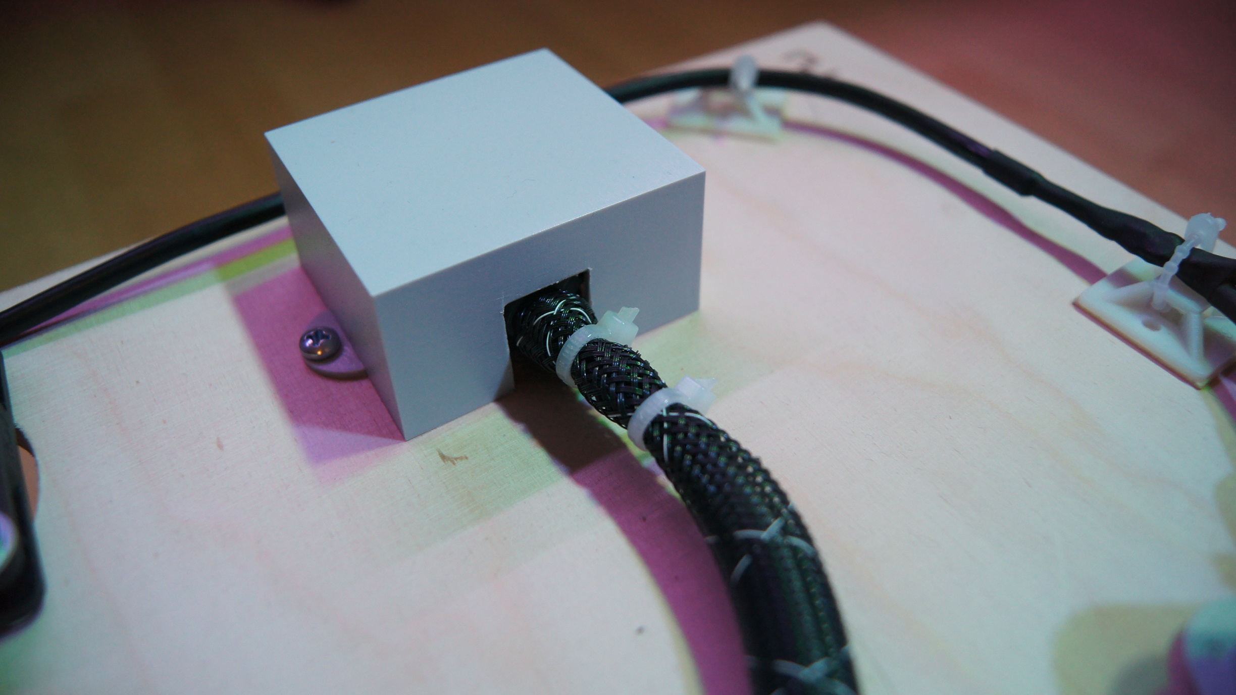
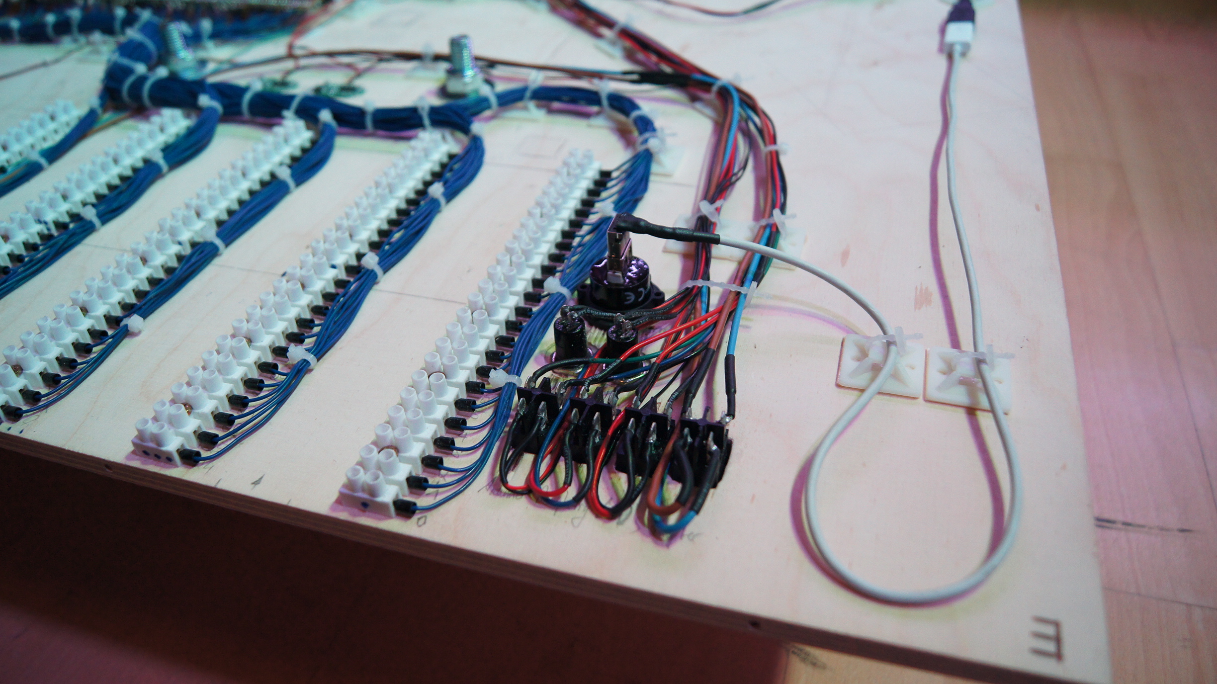
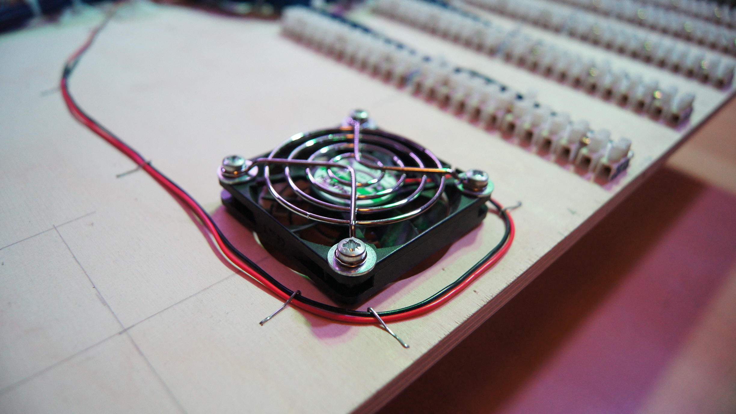
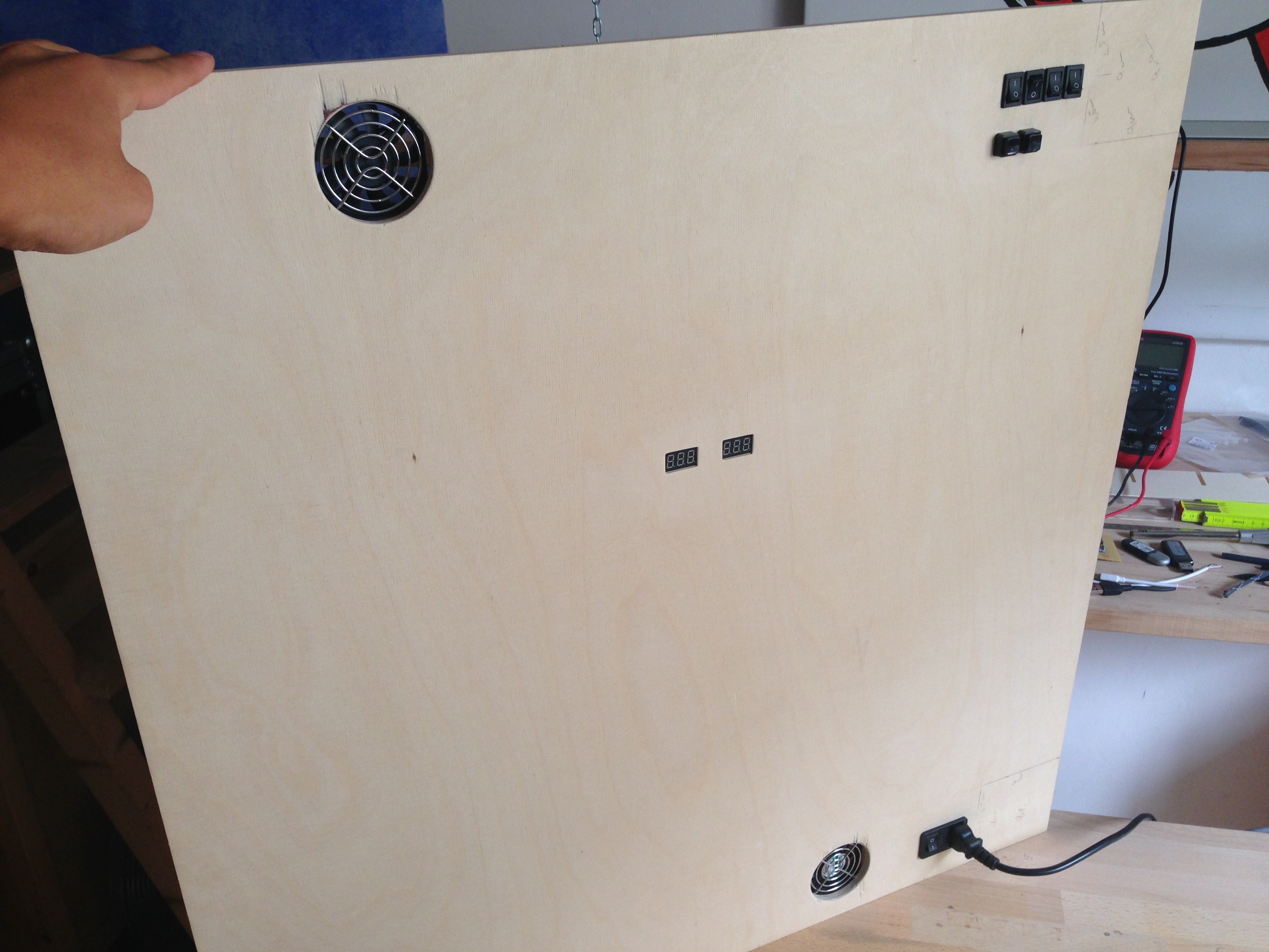
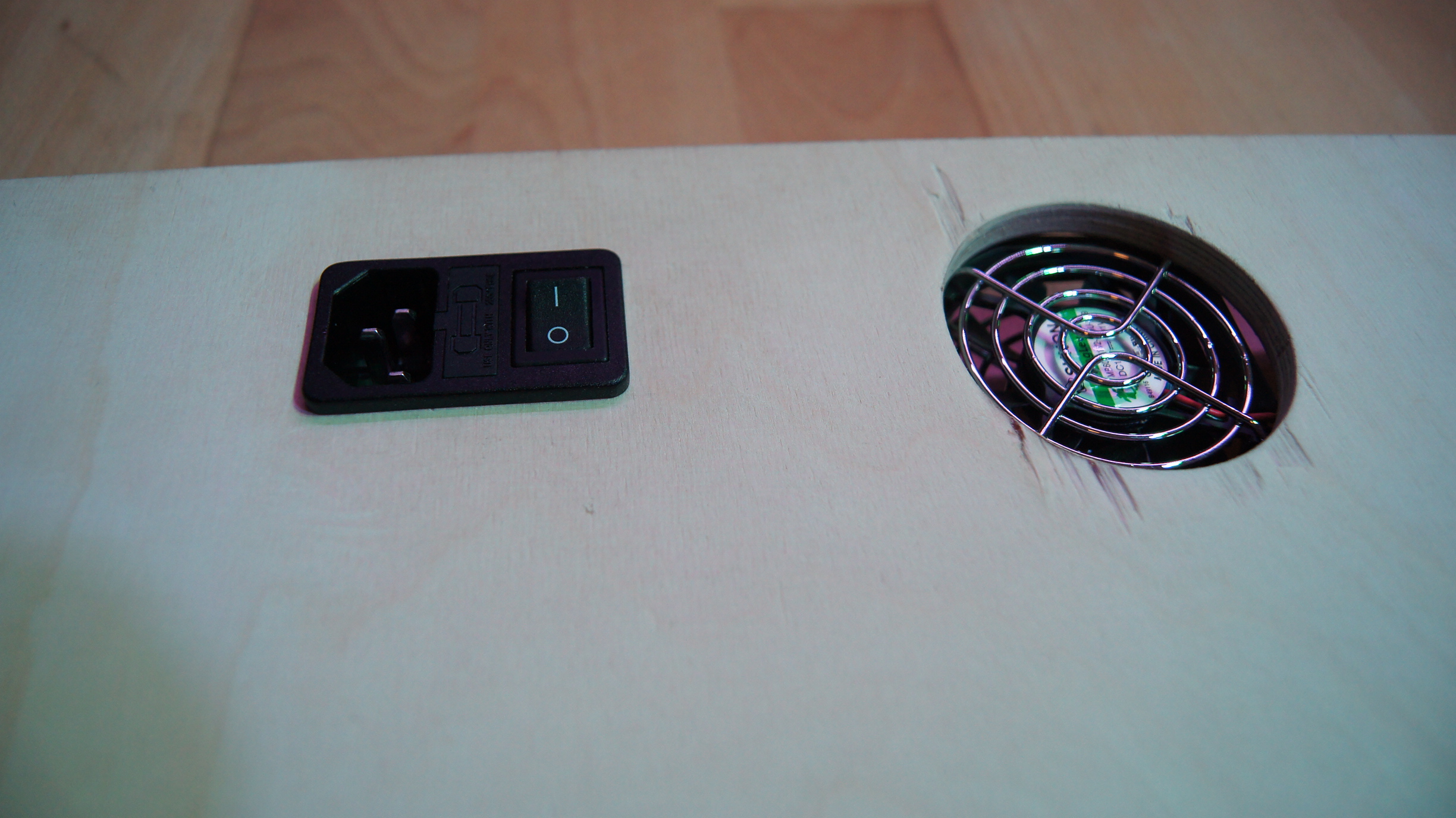
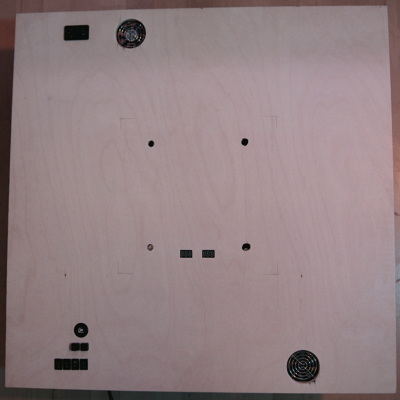
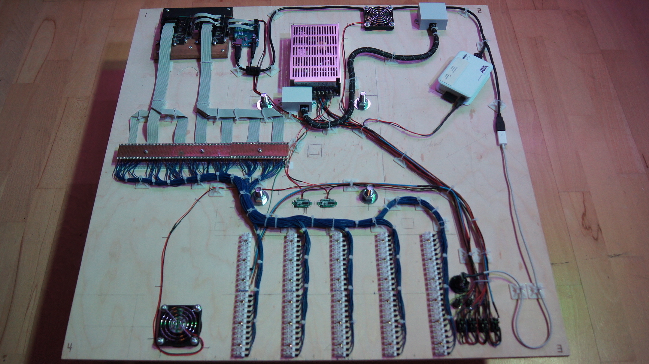
The wiring of the control electronics was somewhat more demanding than that of the circuit boards.
The individual elements to be wired were: 1] The Arduino Uno with the two Macetech Centipede Shield
expansion boards. 2] The power supply (1x 5V / 1x 12V), which supplies the single components with
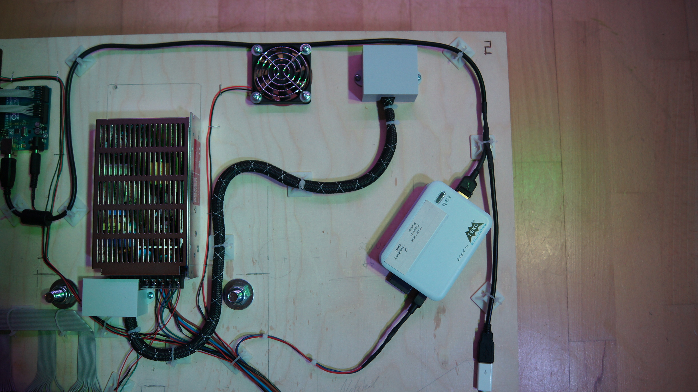
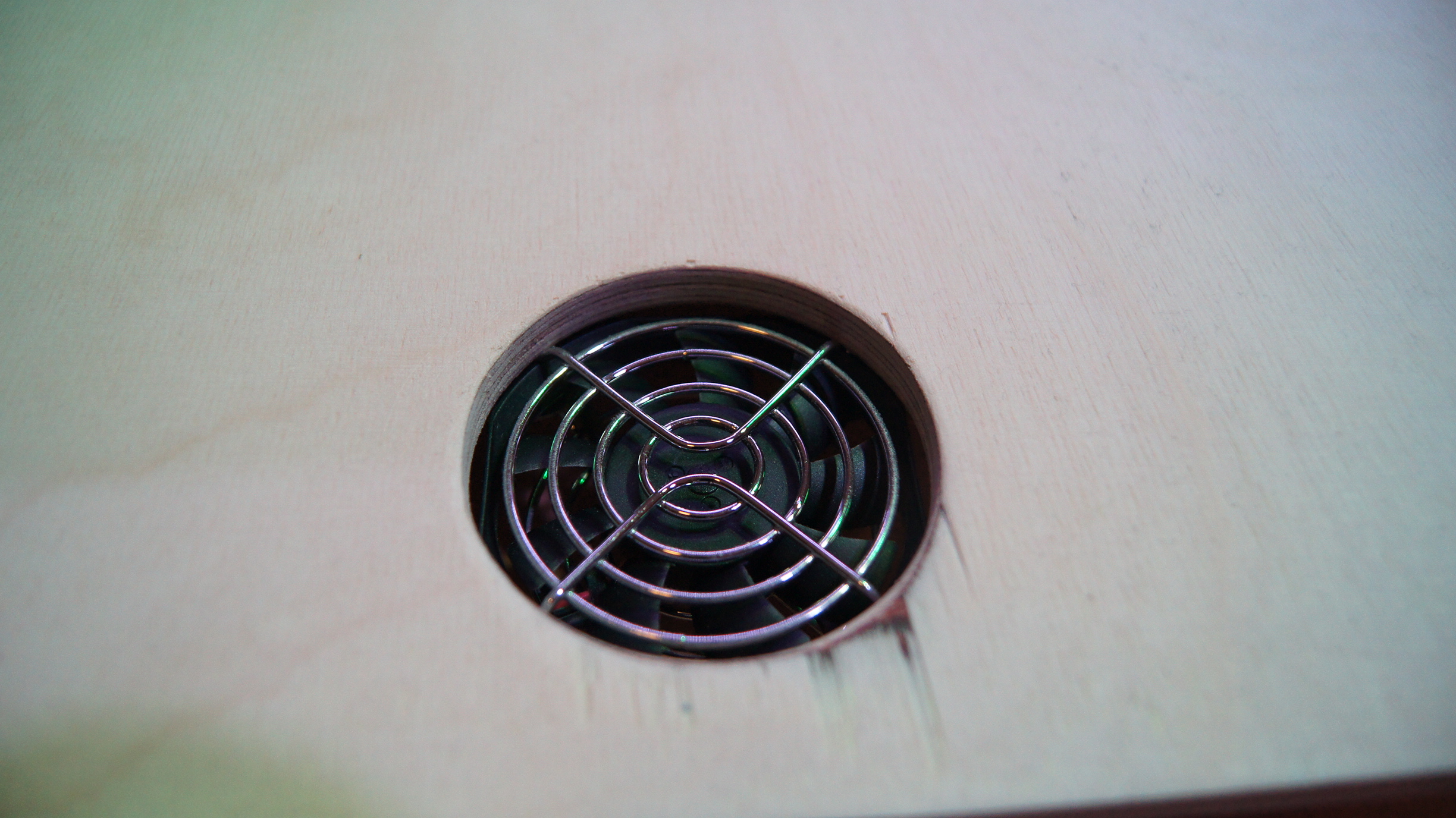
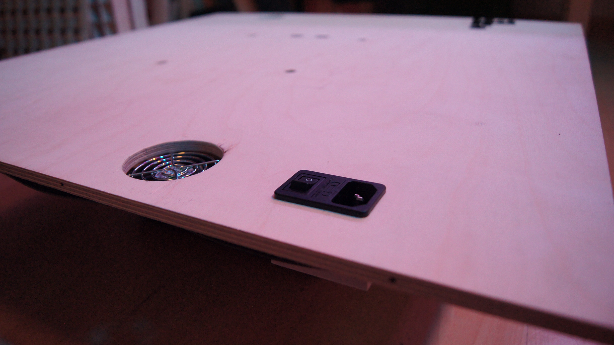
power. 3] Two fans for a little air exchange in the case, because power always means heat. 4] The
cold start cable plug socket for the connection to the socket. 5] A RaspberryPi for later tests,
which unfortunately was never really used:) 6] The "patching board" on which every single touch
signal was connected to the correct digital input on the Arduino Uno or the Macetech Centipede
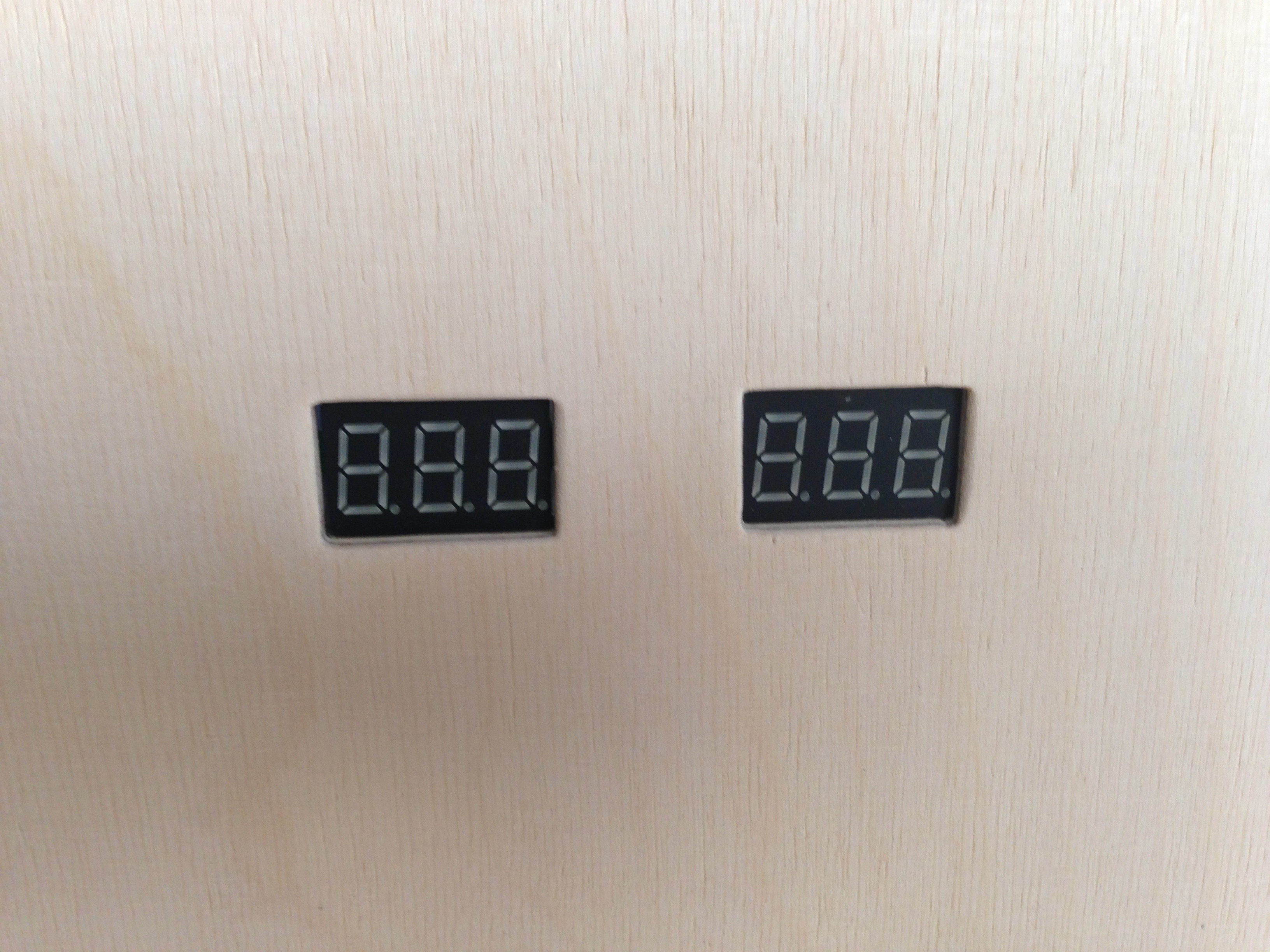
Shield. 7] Two small voltometer voltage indicators to monitor the two voltages from the power
supply. 8] The second side of the Lysterklemmen plug connection to the board plate over which the
100 touch signals, the data pin and the power supply for the boards are transmitted. 9] One USB
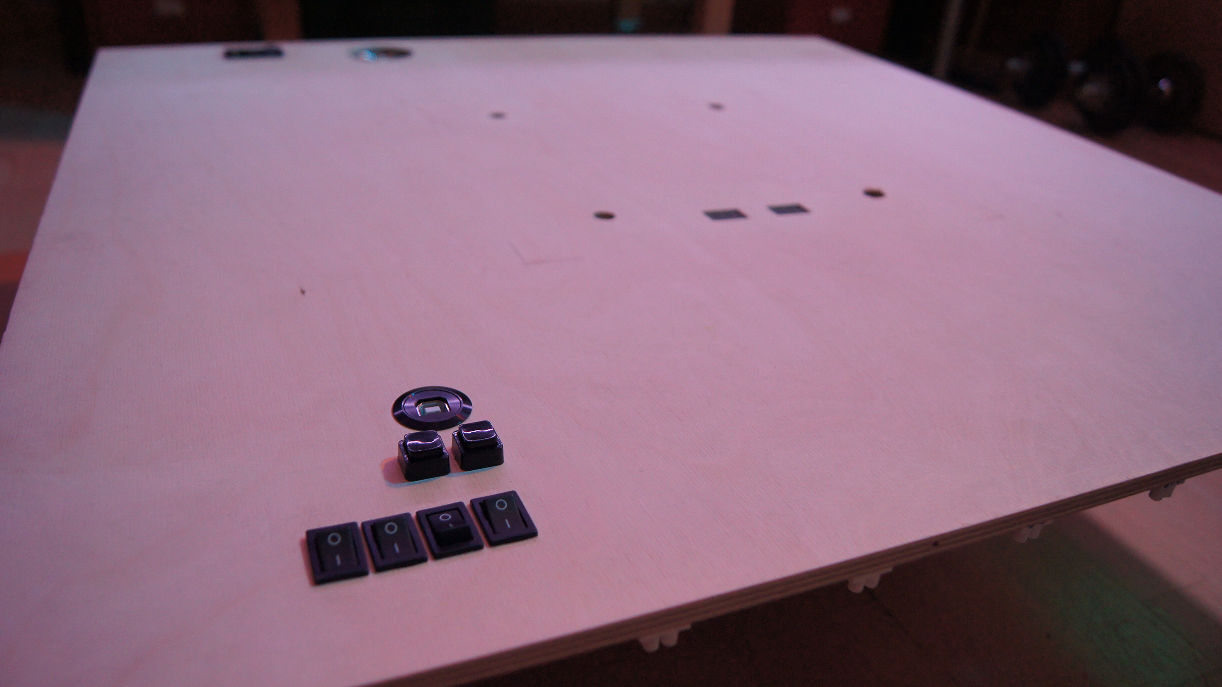
socket for later programming of additional programs for the LED table. 10] Small toggle switches to
switch ON and OFF the individual components (Arduino Uno, RaspberryPi, fan, LED's current) and
buttons to reset the Arduino or to display the voltages at the power supply through the built-in
voltometers.
The time had come! Now I could finally "marry" both big halves of the inner life with each other.
All I had to do was to connect all the lyster terminal plugs and it was done! Just assemble the case
on the outside and the table was as good as finished...
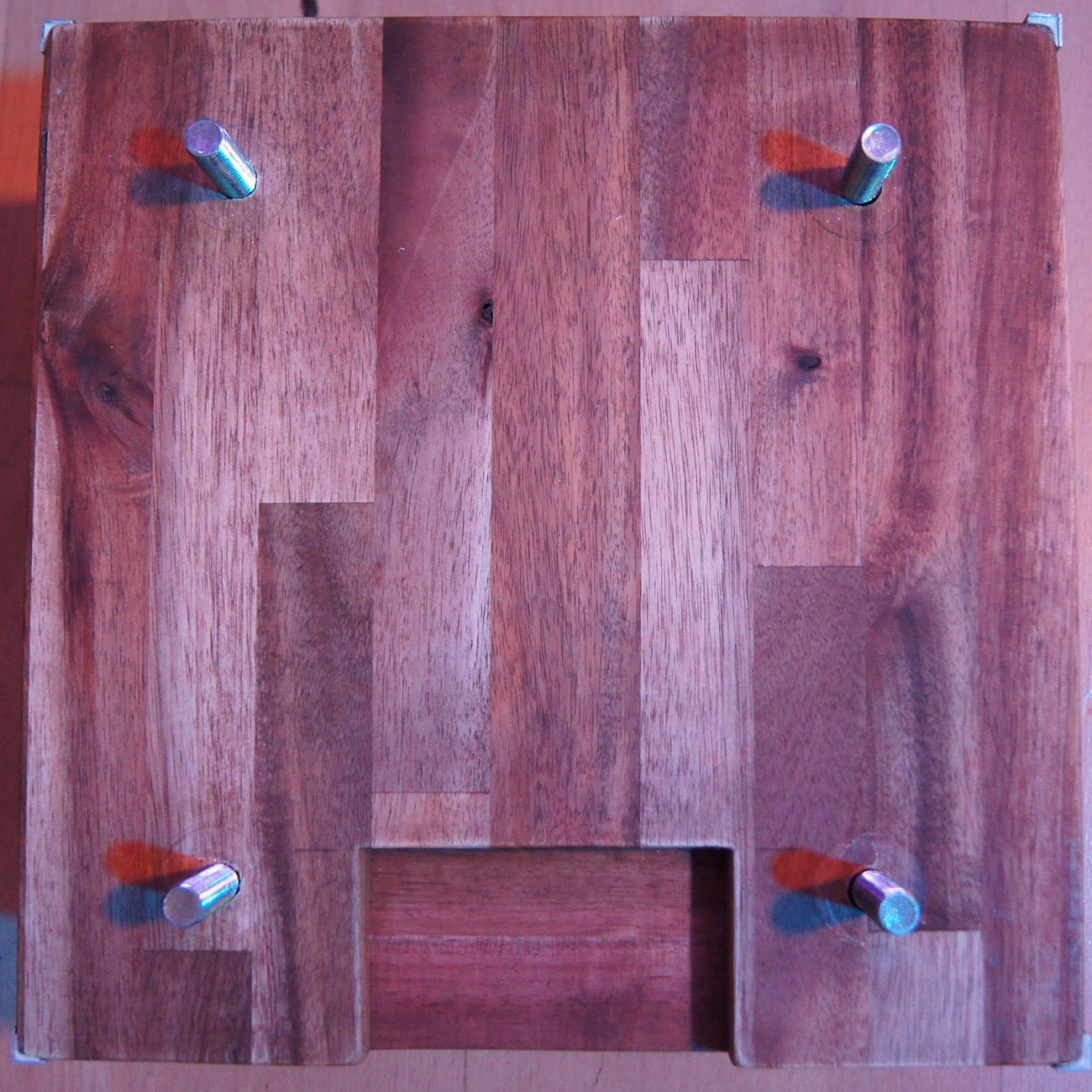
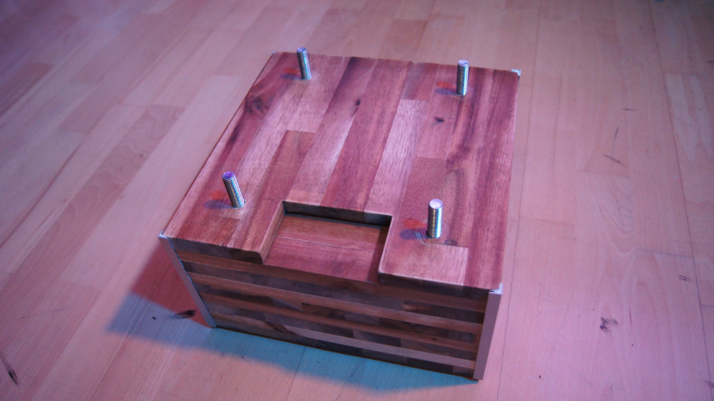
The only thing missing now was a foot for the table, which I built out of 9 layers of 1.8cm thick
acacia wood core boards glued together, from the wood I had left from the frame construction. The
four screws also held the foot together and connected the foot to the rest of the table. The edges
of the foot were finished with four stainless steel corners for optical improvement. I therefore
decided on a massive construction, because a certain weight for such a table is always advantageous
for the stability. Consisting of the base, the base plate with all control electronics, the board
plate, the pixel grid, the frame of the whole table and the Plexiglas plate for the top, the table
was finally finished on the hardware side:) (Click your way through!)
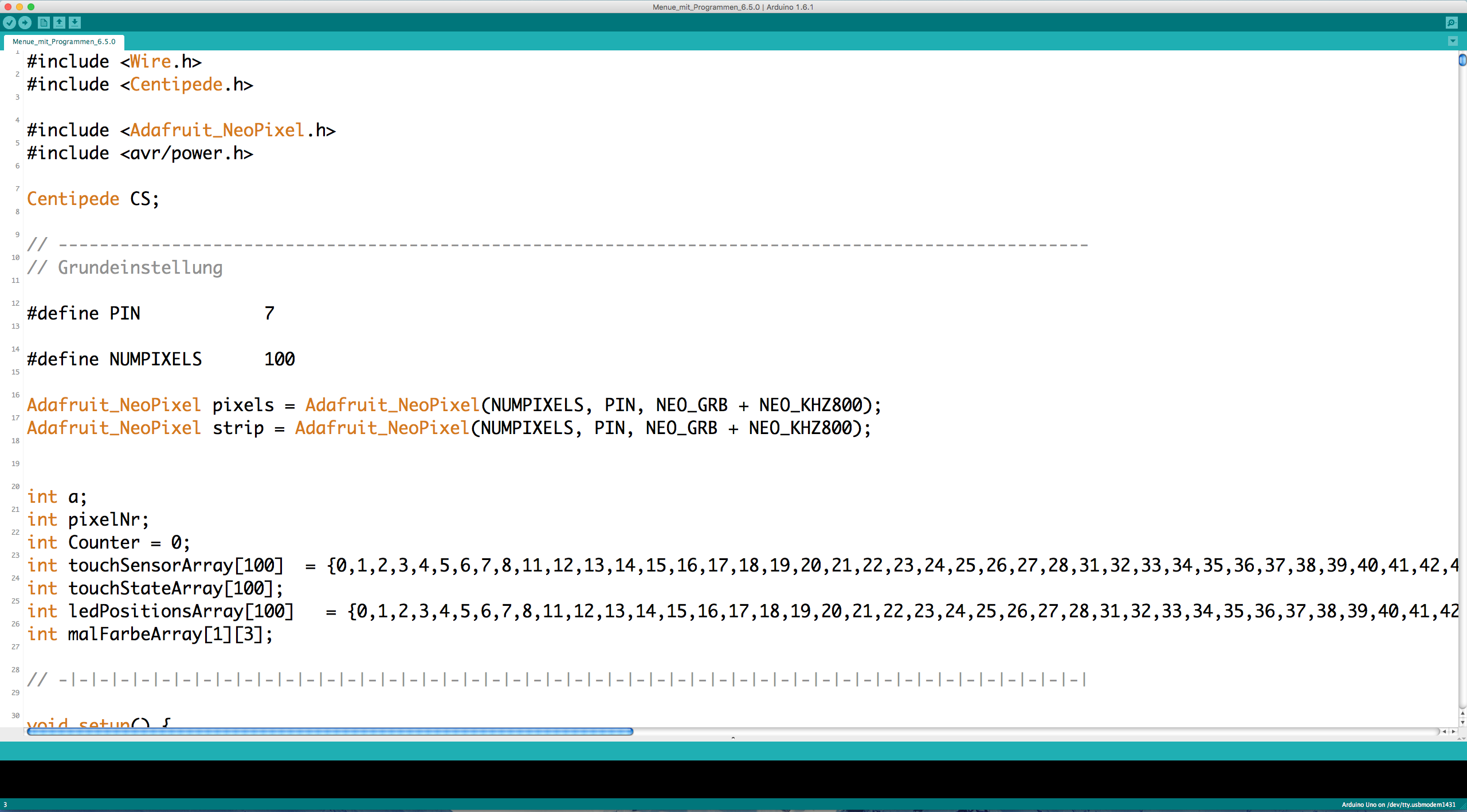
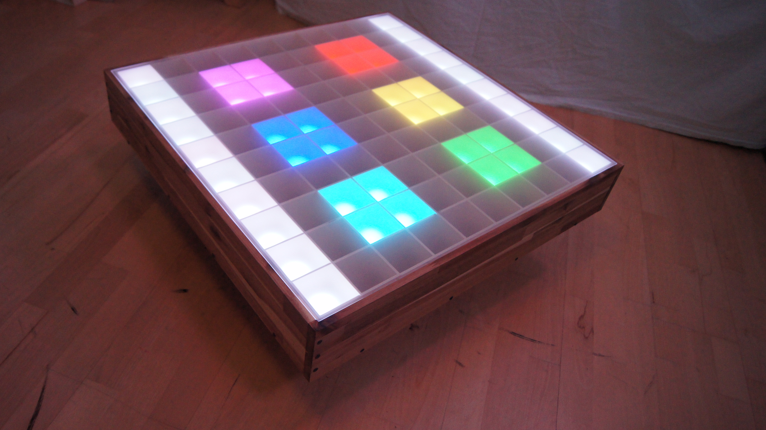
Of course, the software technology was quite different... Not much had happened here yet and all the
more had to be done. So the fun was just beginning. For the programming I took a lot of time, and I
needed that too! Such a program is not even written as fast as you think it is, especially not if
you want to implement everything that comes into your head (including Snake, Tetris, Tic Tac Toe,
etc.). Therefore I programmed without end and continued to look for even better methods to complete
the tasks... Of course I didn't get as far as I had hoped, but for simple color gradients, patterns,
interactive reactions and small painting programs it was still enough for the presentation! Since
then I have been filing and programming at the table and the programs every now and then when there
is time, but if you know something like that, you know that it won't come to a final end:)
That's it, that's it! I made it... In the beginning I never thought that this would really work out
sometime, both the table itself and in the construction phase to achieve this result! It was a
project which demanded a lot of concentration and staying focused and which I also had a lot of fun
with, especially if you now have the finished product in your room and you can look at it every day
with admiration:) Thank you for your great interest and I hope I could help you a little! If you
still have questions or just want to leave me a comment, please contact me via the Contact-Form! I am happy about any feedback.
Thank you for your attention!
Thank you for your attention!